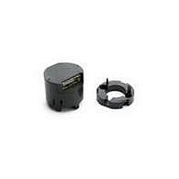
AEDS-8111-E11 Avago Technologies US Inc., AEDS-8111-E11 Datasheet - Page 2

AEDS-8111-E11
Manufacturer Part Number
AEDS-8111-E11
Description
Kit En,M CW,3Ch,200CPR,4mm,Gated 180e
Manufacturer
Avago Technologies US Inc.
Series
AEDx-8xxx-xxxr
Datasheet
1.HEDS-8911-152.pdf
(9 pages)
Specifications of AEDS-8111-E11
Encoder Type
Optical
Output Type
Quadrature with Index (Incremental)
Pulses Per Revolution
200
Voltage - Supply
5VDC
Actuator Type
4mm Open Center
Detent
No
Built In Switch
No
Mounting Type
Chassis Mount, Motors
Termination Style
Terminal Pins
Product
Optical
Lead Free Status / RoHS Status
Lead free / RoHS Compliant
Orientation
-
Rotational Life (cycles Min)
-
Lead Free Status / Rohs Status
Lead free / RoHS Compliant
Absolute Maximum Ratings
Note:
1. Absolute Maximum Ratings are those values beyond which the safety of the device cannot be guaranteed. They are not meant to imply that the
2. Stresses greater than those listed under Absolute Maximum Ratings may cause permanent damage to the device. Exposure to absolute maximum
2
Theory of Operation
The AEDx-8xxx optical encoder is a housed solution with
integrated encoder and codewheel. The encoder trans-
lates the rotary motion of a shaft into incremental digital
outputs.
The encoder contains a single Light Emitting Diode (LED)
as the light source. The light is collimated into a parallel
beam by means of polycarbonate lens located directly
over the LED. Opposite the emitter is a detector IC. This
IC consists of multiple sets of photo detectors and signal
processing circuitry necessary to produce the digital wave-
form output. The codewheel rotates between the emitter
and detector, causing the light beam to be interrupted by
pattern of spaces and bars on the codewheel. The Photo-
diodes that detect these interruptions are arranged in a
pattern that corresponds to the radius and design of the
codewheel. These detectors are also spaced in such way
that light period on one pair of detectors corresponds to
dark period on adjacent pair of detectors. The photodiode
outputs are then fed through the signal processing circuit-
ry that produce the final outputs for channel A and B. Due
to this integrated phasing technique, the digital output of
channel A is in quadrature with that of channel B (90 elec-
trical degrees out of phase). As a standard, the outputs are
fed through a standard RS422 line driver to deliver the dif-
ferentials signals at the final encoder output.
Parameter
1.
2.
3.
4.
5.
6.
device should be operated at these limits.
rating conditions for extended periods may affect reliability.
Storage Temperature AEDT Series
Storage Temperature AEDS Series
Supply Voltage
Output Voltage
Output Current per Channel
Shaft Axial Play
Shaft Radial Play Plus Eccentricity
[1,2]
Symbol Min.
T
T
Vcc
Vout
Iout
S
S
-20
-40
-0.5
-0.5
-
-
-
Definitions
Cycles (N): The number of electrical cycles per revolution
(CPR).
Note: CPR refers to the raw signal from encoder, that is
the cycles before 4x decode.
One Cycle: 360 electrical degrees (°e).
One Shaft Rotation: 360 mechanical degrees.
Cycle Error (∆C): An indication of cycle uniformity. The dif-
ference between an observed shaft angle which gives
rise to one electrical cycle, and the nominal angular
increment of 1/N of a revolution.
Pulse Width (P): The number of electrical degrees that an
output is high during 1 cycle. This value is nominally
180°e or 1/2 cycle.
Pulse Width Error (∆P): The deviation, in electrical degrees,
of the pulse width from its ideal value of 180°e.
State Width (S): The numbers of electrical degrees be-
tween transitions in the output of channel A and the
neighboring transition in the output of channel B. There
are 4 states per cycle, each nominally 90°e.
State Width Error (∆S): The deviation, in electrical degrees,
of each state width from its ideal value of 90°e.
Phase (Φ): The numbers of electrical degrees between
the center of the high state of channel A and the center
of the high state of channel B. This value is nominally
90°e for quadrature output.
Phase Error (∆φ): The deviation of the phase from its ideal
value of 90°e.
Index Pulse Width (Po): The number of electrical degrees
that an index is high with reference to channel A or
channel B during one full shaft rotation.
Max.
85
100
7
Vcc
± 150
± 0.100 mm
± 0.080 mm
Units
° C
° C
V
V
mA


