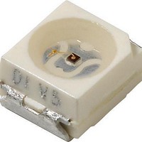
VLMO33S1T2-GS18 Vishay, VLMO33S1T2-GS18 Datasheet
VLMO33S1T2-GS18
Specifications of VLMO33S1T2-GS18


Related parts for VLMO33S1T2-GS18

VLMO33S1T2-GS18 Summary of contents
Page 1
... PART VLMR33T1U2-GS08 VLMR33T1U2-GS18 VLMR33R2U2-GS08 VLMR33R2U2-GS18 VLMS33S1T2-GS08 VLMS33S1T2-GS18 VLMS33S1U1-GS08 VLMS33S1U1-GS18 VLMO33S1T2-GS08 VLMO33S1T2-GS18 VLMO33T1U2-GS08 VLMO33T1U2-GS18 ** Please see document “Vishay Material Category Policy”: Document Number 81336 Rev. 1.1, 22-Feb-11 Power SMD LED PLCC-2 FEATURES • Utilizing (AS) AlInGaP technology • Available tape • Luminous intensity and color categorized per packing unit • ...
Page 2
... VLM.33.. Vishay Semiconductors PARTS TABLE PART VLMO33R2U2-GS08 VLMO33R2U2-GS18 VLMY33T1U2-GS08 VLMY33T1U2-GS18 VLMY33R2U2-GS08 VLMY33R2U2-GS18 ABSOLUTE MAXIMUM RATINGS (T PARAMETER 1) Reverse voltage T DC forward current Power dissipation Junction temperature Operating temperature range Storage temperature range Thermal resistance junction/ Mounted on PC board ambient Note: 1) Driving the LED in reverse direction is suitable for a short term application OPTICAL AND ELECTRICAL CHARACTERISTICS (T VLMR33 ...
Page 3
... Forward voltage Reverse current Document Number 81336 Rev. 1.1, 22-Feb- °C, unless otherwise specified) amb TEST CONDITION PART VLMS33S1T2 VLMS33S1U1 °C, unless otherwise specified) amb TEST CONDITION PART VLMO33S1T2 VLMO33T1U2 F VLMO33R2U2 °C, unless otherwise specified) amb TEST CONDITION PART VLMY33T1U2 VLMY33R2U2 ...
Page 4
... VLM.33.. Vishay Semiconductors COLOR CLASSIFICATION GROUP AMBER MIN. 1 611 2 614 Note: Wavelengths are tested at a current pulse duration of 25 ms. LUMINOUS INTENSITY CLASSIFICATION GROUP LUMINOUS INTENSITY (mcd) STANDARD OPTIONAL MIN 112 R 2 140 1 180 S 2 224 1 280 T 2 355 1 450 U 2 560 ...
Page 5
... Figure 6. Relative Luminous Intensity vs. Forward Current For technical support, please contact: LED@vishay.com VLM.33.. Vishay Semiconductors 100 90 yellow 80 soft orange amber 70 super red 1.5 1.6 1.7 1.8 1.9 2.0 2.1 2.2 2.3 2.4 2.5 ...
Page 6
... VLM.33.. Vishay Semiconductors 2.5 amber 2.0 1.5 1.0 0.5 0 Ambient Temperature (°C) 20197 amb Figure 7. Relative Luminous Intensity vs. Amb. Temperature 6 amber Ambient Temperature (°C) 20199 amb Figure 8. Change of Dominant Wavelength vs. Ambient Temperature 250 200 50 mA 150 100 100 - 150 - 200 - Ambient Temperature (°C) ...
Page 7
... Rev. 1.1, 22-Feb-11 75 100 17021 Figure 16. Relative Luminous Intensity vs. Amb. Temperature super red 75 100 640 660 17020 Figure 18. Change of Forward Voltage vs. Ambient Temperature For technical support, please contact: LED@vishay.com VLM.33.. Vishay Semiconductors 2.5 soft orange 2.0 1.5 1.0 0.5 0 Ambient Temperature (°C) ...
Page 8
... VLM.33.. Vishay Semiconductors 1.2 yellow 1.0 0.8 0.6 0.4 0.2 0 540 560 580 600 λ - Wavelength (nm) 16008 Figure 19. Relative Intensity vs. Wavelength 2.5 yellow 2.0 1.5 1.0 0.5 0 Ambient Temperature (°C) 17016 amb Figure 20. Relative Luminous Intensity vs. Amb. Temperature PACKAGE DIMENSIONS in millimeters C Drawing-No ...
Page 9
... METHOD OF TAPING/POLARITY AND TAPE AND REEL SMD LED (VLM3 - SERIES) Vishay’s LEDs in SMD packages are available in an antistatic 8 mm blister tape (in accordance with DIN IEC 40 (CO) 564) for automatic component insertion. The blister tape is a plastic strip with impressed component cavities, covered by a top tape. ...
Page 10
... Time (s) 19885 Figure 26. Vishay Lead (Pb)-free Reflow Soldering Profile (acc. to J-STD-020) TTW Soldering (acc. to CECC00802) 300 5 s lead temperature 250 235 °C second full line: typical wave to 260 °C ...
Page 11
... Electro-static sensitive devices warning labels are on the packaging. VISHAY BAR CODE LABELS The Vishay Semiconductors standard bar-code labels are printed at final packing areas. The labels are on each packing unit and contain Vishay Semiconductors specific data. For technical support, please contact: LED@vishay.com VLM.33.. Vishay Semiconductors ...
Page 12
... Vishay product could result in personal injury or death. Customers using or selling Vishay products not expressly indicated for use in such applications their own risk and agree to fully indemnify and hold Vishay and its distributors harmless from and against any and all claims, liabilities, expenses and damages arising or resulting in connection with such use or sale, including attorneys fees, even if such claim alleges that Vishay or its distributor was negligent regarding the design or manufacture of the part ...