ER400RS EASY RADIO, ER400RS Datasheet - Page 4
ER400RS
Manufacturer Part Number
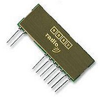
ER400RS
Description
MODULE, RX, FM, 433MHZ
Manufacturer
EASY RADIO
Datasheet
1.ER400RS.pdf
(15 pages)
Specifications of ER400RS
External Depth
4mm
External Length / Height
14mm
External Width
37mm
Frequency
433MHz
Operating Temperature Max
65°C
Operating Temperature Min
-20°C
Rf Sensitivity
-105dBm
Range
250m


Pin Description
Checklist
Application & Operation ER400TS & RS
Figure 5 shows a typical system block diagram comprising hosts (user’s application) connected to Easy-
Radio Transmitters and Receivers. Host (A) will be monitoring (collecting data) and Host (B) will be receiving
and processing this data.
The Host (A) should provide the serial data input (up to a maximum 128 characters per packet) to the Easy-
Radio transmitter. The data should be sent in ‘bursts’ therefore allowing adequate time for transmission and
reception over the RF link (See Figure 6). The receiver, upon reception and decoding of the RF transmission
immediately sends serial data to the Host B.
Data is sent and received in standard ‘RS232’ serial format (logic level only) and there is no restriction on the
characters that may be sent.
LPRS Data Sheet
Pin
No
1
2
3
4
5
6
7
8
9
Easy -Radio ER400TS, ER400RS & ER400TRS 1-1.doc
1. The module operates internally from an on board 3.3 Volt low drop regulator. The logic levels of the
2. All digital inputs and outputs are intended for connection to low voltage logic devices. Do not connect
3. Outputs will drive logic operating at 5 Volts.
4. If in handshaking mode, pin (7) of the ER400RS module should be connected directly to GND for
input/output pins are therefore between 0 Volt and 3.3 Volts. (See RS Performance Data).
any of the inputs o r outputs directly to an RS232 port. The receiver module may be permanently
damaged by the voltages (+/- 12V) present on RS232 signal lines. See Application Circuit (Figure
11) for typical connection to an RS232 port via MAX232 interface IC.
data to be delivered.
Name
Antenna
RF Ground
RSSI
BSY
Data Out
Data In
RDY
Vcc
Ground
Host
(A)
Transmit Data (TXD)
Easy -Radio ER400TS Transmitter, ER400RS Receiver & ER400TRS Transceiver
Description
50 Ohm RF input/output. Connect to suitable antenna.
RF ground. Connect to antenna ground (coaxial cable screen
braid) and local ground plane. Internally connected to other
Ground pins.
Received Signal Strength Indication - Analogue
Output (Low - Ready for data from Host) (High - Not Ready)
Received Data Output
ER command Input
Input (Low – Host Ready to receive data) (High – Not Ready)
Positive supply pin. +3.6 to +5.5 Volts. This should be a
‘clean’ noise free supply with less than 25mV of ripple.
Connect to supply 0 Volt and ground plane
Figure 5 Typical System Block Diagram
Transmitter
Easy-Radio
RF Link
Copyright LPRS 2003. March2004
Easy-Radio
Receiver
Receive Data Output
Host
(B)
Notes
See Note
See Note
CTS function
SDO
SDI
RTS function
Page 4 of 15
Related parts for ER400RS
Image
Part Number
Description
Manufacturer
Datasheet
Request
R

Part Number:
Description:
EVALUATION KIT, EASY RADIO
Manufacturer:
EASY RADIO
Datasheet:

Part Number:
Description:
MODULE, RECEIVER, EASY RADIO
Manufacturer:
EASY RADIO
Datasheet:

Part Number:
Description:
TRANSMITTER, EASY RADIO, 2BUTTON, 434MHZ
Manufacturer:
EASY RADIO
Datasheet:

Part Number:
Description:
MODULE, TX, 433MHZ
Manufacturer:
EASY RADIO
Datasheet:
