F-S-W EVERETT CHARLES TECH, F-S-W Datasheet
F-S-W
Specifications of F-S-W


F-S-W Summary of contents
Page 1
... Pogo Contacts for Board Test, Battery Interconnects, Medical Devices and other Momentary Electrical Contacts ® ...
Page 2
... F 1 The figure above depicts the biasing angle (ø), spring force (F), radial or side force ( and plunger force ( Biasing-Ball Pogo Contacts. Contact Resistance In evaluating contact resistance, low levels of resistance are important. However, the more critical performance measurement is the consistency of the low contact resistance ...
Page 3
... P2665 Series - .125 (3.18) centers . . . . . . . . . . . .8 P2757 Series - .187 (4.75) centers . . . . . . . . . . . .9 Nonreplaceable Pogo Contacts . . . . . . . . . . . . . .10 Pogo Contact A-A-S/A-S Series . . . . . . . . . . . . .11 Pogo Contact C-S/E-S Series . . . . . . . . . . . . . . .12 Pogo Contact F/G Series . . . . . . . . . . . . . . . . . . .13 Pogo Contact P2550/P2532 Series . . . . . . . . . .14 Pogo Contact Low Ω/P2447/HC125A- .15 Pogo Contact P3325 Series/P4301- .16 Tools . . . . . . . . . . . . . . . . . . . . . . . . . . . . . . . . . . .17 Custom-designed Pogo Contacts ...
Page 4
... Body . . . . . . . . . . . . . . . . . . . . . . . . . . . . . . Gold-plated phosphorous bronze Spring . . . . . . . . . . . . . . . . . . . . . . . . . . . . . Silver-plated BeCu Ball . . . . . . . . . . . . . . . . . . . . . . . . . . . . . . . Stainless steel Electrical Resistance . . . . . . . . . . . . . . . . . . <30mΩ Maximum Current . . . . . . . . . . . . . . . . . . . . 3 amps Working Travel . . . . . . . . . . . . . . . . . . . . . . . .067” (1.7) Spring Force in oz. (grams) Standard 0.7 (20) Alternate 0.6 (17) Pogo ® Receptacle The P2662A Series is designed to be used with the S2662A Series receptacle below. ...
Page 5
... Pogo ® Receptacle The P2662B Series is designed to be used with the PR261 Series receptacles below. The recommended mounting hole is .035/.0365 (0.89/0.93mm). The recommended drill is a #64 or 0.92mm. Use tool T261-0 for installation. PR261-O Crimp .180 (4.57) .034 (0.86) TYP MIN ...
Page 6
... Body . . . . . . . . . . . . . . . . . . . . . . . . . . . . . . Gold-plated phosphorous bronze Spring . . . . . . . . . . . . . . . . . . . . . . . . . . . . . Stainless steel Ball . . . . . . . . . . . . . . . . . . . . . . . . . . . . . . . Stainless steel Electrical Resistance . . . . . . . . . . . . . . . . . . <10mΩ Maximum Current . . . . . . . . . . . . . . . . . . . . 3 amps Working Travel . . . . . . . . . . . . . . . . . . . . . . . .067” (1.70) Spring Force in oz. (grams) Standard 1.5 (42) Alternate 1.0 (28) Pogo ® Receptacle The P2663 Series is designed to be used with the S2663 Series receptacles below. ...
Page 7
... Alternate 3.0 (85) Pogo ® Receptacle The P2664 Series is designed to be used with the PR541 Series receptacles below. The recommended mounting hole is .069 (1.75mm). The recommended drill is 1.75mm. Use ARIT54 tool for installation. PR541-O Crimp .066 (1.68) TYP .20 (5.08) .240 (6.09) MIN TYP ...
Page 8
... Alternate 1.3 (37) Pogo ® Receptacle The P3158 Series is designed to be used with the PR541 Series receptacles below. The recommended mounting hole is .069 (1.75mm). The recommended drill is 1.75mm. Use ARIT54 tool for installation. PR541-O Crimp .066 (1.68) TYP .20 (5.08) .240 (6.09) MIN TYP ...
Page 9
... Alternate (-3 2.5 (71) ® Pogo Receptacle The P5160 Series is designed to be used with the PR54 Series receptacles below. The recommended mounting hole is .069 (1.75mm). The recommended drill is 1.75mm. Use ARIT54 tool for installation. .066 (1.68) PR54-O Crimp TYP .300 (7.62) TYP .180 (4.57) MIN 1 ...
Page 10
... Pogo ® Receptacle The P2665 Series is designed to be used with the PR80 Series receptacles below. The recommended mounting hole is .094/.096 (2.39/2.44mm). The recommended drill is a #41 or 2.4mm. Use tool T80-0 for installation. .093 (2.36) PR80-O Crimp TYP .300 (7.62) TYP ...
Page 11
... Body . . . . . . . . . . . . . . . . . . . . . . . . . . . . . . Gold-plated phosphorous bronze Spring . . . . . . . . . . . . . . . . . . . . . . . . . . . . . Stainless steel Ball . . . . . . . . . . . . . . . . . . . . . . . . . . . . . . . Stainless steel Electrical Resistance . . . . . . . . . . . . . . . . . . <10mΩ Maximum Current . . . . . . . . . . . . . . . . . . . . 20 amps Working Travel . . . . . . . . . . . . . . . . . . . . . . . .167” (4.24) Spring Force in oz. (grams) Standard (57) Alternate (Stainless steel 3.5 (99) Pogo ® Receptacle The P2757 Series is designed to be used with the S2757 Series receptacles below. ...
Page 12
... Nonreplaceable Pogo The Pylon line of standard products include nonreplaceable Pogo Contacts. They differ from the replaceable contacts in that they do not require a socket. The nonreplaceable line is designed to be permanently mounted. Solder pots are incorporated for a reliable electrical connection. The construction is typically gold-plated brass bodies, combined with gold-plated springs and plungers ...
Page 13
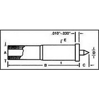
... Spring . . . . . . . . . . . . . . . . . . . . . . . . . . . . . Gold-plated stainless steel Ball . . . . . . . . . . . . . . . . . . . . . . . . . . . . . . . Gold-plated stainless steel Electrical Resistance . . . . . . . . . . . . . . . . . . <30mΩ Maximum Current . . . . . . . . . . . . . . . . . . . . 2 amps Working Travel . . . . . . . . . . . . . . . . . . . . . . . .020 (0.51) Spring Force in oz. (grams) Standard 0.7 (20) The recommended hole is .0380 (#62 drill) for epoxy mounting. A-A-S/A-S Series .030 (0.76) .030 (0.76) Travel Initial Working 2.0 (57) ...
Page 14
... Ball . . . . . . . . . . . . . . . . . . . . . . . . . . . . . . . Gold-plated stainless steel Electrical Resistance . . . . . . . . . . . . . . . . . . <30mΩ Maximum Current . . . . . . . . . . . . . . . . . . . . 5 amps Working Travel . . . . . . . . . . . . . . . . . . . . . . . .043 (1.09) Spring Force in oz. (grams) Standard 1.0 (29) The recommended hole is .0670 (#51 drill) for epoxy mounting. .049 (1.24) .045 (1.14) .020 (0.51) .045 (1.14) Travel .395 (10.03) Initial Working 3 ...
Page 15
... Ball . . . . . . . . . . . . . . . . . . . . . . . . . . . . . . . Gold-plated stainless steel Electrical Resistance . . . . . . . . . . . . . . . . . . <30mΩ Maximum Current . . . . . . . . . . . . . . . . . . . . 5 amps Working Travel . . . . . . . . . . . . . . . . . . . . . . . .066 (1.68) Spring Force in oz. (grams) Standard 2.0 (57) The recommended hole is .0860 (#44 drill) for epoxy mounting. .043 (1.09) x .150 (3.81) Deep .082 (2.08) Solder Pot .066 (1.68) .780 (19.81) G-S Series Specifications Plunger ...
Page 16
... Ball . . . . . . . . . . . . . . . . . . . . . . . . . . . . . . . Gold-plated stainless steel Electrical Resistance . . . . . . . . . . . . . . . . . . <30mΩ Maximum Current . . . . . . . . . . . . . . . . . . . . 5 amps Working Travel . . . . . . . . . . . . . . . . . . . . . . . .093 (2.36) Spring Force in oz. (grams) Standard 1.0 (28) The recommended hole is .0945 (2.4mm) for epoxy mounting. * Consult factory for minimum order quantity * .150 (3.81) .125 (3.18) .375 (9.52) ...
Page 17
... Spring . . . . . . . . . . . . . . . . . . . . . . . . . . . . . Silver-plated stainless steel Electrical Resistance . . . . . . . . . . . . . . . . . . <20mΩ Maximum Current . . . . . . . . . . . . . . . . . . . . 45 amps Plunger Travel (Full .250 (6.35) The HC125A-TT is designed to be used with the SR125 receptacle. The recommended mounting hole is .141/.143 (3.58/3.63mm). The recommended drill is a 3.6mm. Use tool T125-0 for installation. ...
Page 18
... Spring . . . . . . . . . . . . . . . . . . . . . . . . . . . . . Stainless steel Ball . . . . . . . . . . . . . . . . . . . . . . . . . . . . . . . Stainless steel Electrical Resistance . . . . . . . . . . . . . . . . . . <5mΩ Maximum Current . . . . . . . . . . . . . . . . . . . . 45 amps Working Travel . . . . . . . . . . . . . . . . . . . . . . . .167 (4.24) Spring Force in oz. (grams) Standard 16.0 (454) The recommended hole is .1890 (#12 drill) for epoxy mounting. .092 (2.34) .085 (2.16) .100 (2.54) .030 (0.76) Travel .645 (16.38) ...
Page 19
... Nylon brush (6-1/4") plates that are 3/8 inch thick or more. If the probe plate is too thin, the receptacle may fall through during insertion. In this case you can drill a smaller hole and use the press ring as a stop ...
Page 20
... Ostby Barton A Division of Everett Charles Technologies 487 Jefferson Boulevard Warwick, RI 02886 Tel: (401) 739-7310 Fax: (401) 732-4937 www.ectinfo.com www.ectinfo.com ©2006 Everett Charles Technologies. Pogo is a registered trademark of ECT.1331-4-06. ...