200-6310-9UN-1900 3M, 200-6310-9UN-1900 Datasheet - Page 2
200-6310-9UN-1900
Manufacturer Part Number
200-6310-9UN-1900
Description
SOCKET PGA ZIP 10X10 MATRIX
Manufacturer
3M
Series
Textool™r
Type
PGA, ZIF (ZIP)r
Datasheet
1.200-6315-9UN-1900.pdf
(2 pages)
Specifications of 200-6310-9UN-1900
Number Of Positions Or Pins (grid)
100 (10 x 10)
Mounting Type
Through Hole
Features
Closed Frame, Without Contacts
Contact Finish
Gold
Contact Finish Thickness
30µin (0.76µm)
Product
PGA Sockets
Lead Free Status / RoHS Status
Lead free / RoHS Compliant
Pitch
-
Lead Free Status / Rohs Status
Lead free / RoHS Compliant
Other names
0 51138 69658 0
20063109UN1900
3M5066
5113869658
51138696580
JE150901237
20063109UN1900
3M5066
5113869658
51138696580
JE150901237


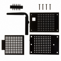
Test & Burn-In PGA Kit Socket
Pin Grid Arrays
3M Electronic Handling and Protection Division
6801 River Place Blvd.
Austin, TX 78726-9000
Ordering Information
Notes:
1 Contact and extra Hole Plugs are ordered separately.
2 See Test & Burn-In PGA socket section on page 29 for dimensional information on assembled sockets.
( Order Separately )
Contact
1
10X Hole Plugs
Cam Plate
Top Plate
Base Plate
200-6310-9UN-1900
200-6313-9UN-1900
200-6315-9UN-1900
200-6317-9UN-1900
200-6319-9UN-1900
200-6321-9UN-1900
200-6325-9UN-1900
300-6300-CNA-0002B
200-4660-14-1900
200-6311-9UN-1900
Part Number
4X Phillips Pan-Hd
#0-80 x 5/16 Long
Assy Screw
Cam Handle
For technical, sales or ordering information call 800-328-0411
Matrix Size
Set of 10
10 x 10
11 x 11
13 x 13
15 x 15
17 x 17
19 x 19
21 x 21
25 x 25
Each
Standard
Handle
or visit our website: http://www.3M.com/ehpd
Contact–BeCu/Au Plated
S k t Kit W/O C t t
Socket Kit W/O Contacts
Extra Hole Plugs
Description
1. Load hole plugs into top plate by
2. Place cam plate into recessed
3. Insert cam handle into position
4. Now make a final check that all
5. Now make an operation check
pressing fitting into place.
Remove from tie bar by cutting
with commercially available 6 1/2
flush diagonal cutter pliers.
area of base plate, load
contacts in desired locations,
being careful that the bent leaf
of the contact is loaded in
correct position ( away from
cam handle. )
in the base plate.
contacts are in desired location
and that all are fairly even at the
top. Also check cam to make
sure it is still in position. Now
take the top plate and place into
position and start to lower over
contacts. Start at the rear of the
socket and rotate downward
toward the front and then snap
locating bosses into place.
Several very slight back and
forth motions may be necessary
in order to get contacts to snap
into place. Care should be taken
that too much downward
pressure isn't applied which
could bend or damage the
contacts. Insert screws and
tighten.
by rotating handle 90
visual check of movement and
closure of all contacts. Rotate
handle and check the freedom
of movement of cam plate and
that the moving leaf of the
contact clears the entry hole. A
continuity check can be made
before final soldering by placing
device in socket, then closing
and making check. Soldering
should be done with socket in
the open position.
Assembly Instructions
∞
. Make a
TS-0675-09
Sheet 2 of 2
"
Related parts for 200-6310-9UN-1900
Image
Part Number
Description
Manufacturer
Datasheet
Request
R

Part Number:
Description:
ANTENNA, GPS, 3M CABLE, SMA
Manufacturer:
WI-SYS
Datasheet:
Part Number:
Description:
ANTENNA, GPS, 3M CABLE, SMA
Manufacturer:
WI-SYS
Datasheet:
Part Number:
Description:
ANTENNA, GPS, 3M CABLE, SMA
Manufacturer:
WI-SYS
Datasheet:

Part Number:
Description:
3M MPro Car Charger
Manufacturer:
3M
Datasheet:

Part Number:
Description:
3M MPro Component Video Cable
Manufacturer:
3M
Datasheet:

Part Number:
Description:
3M-MINI-CLAMP/PLUG/WMIC/2MM/3POS/TYPE A/ORANGE/3M LOGO
Manufacturer:
3M
Datasheet:
Part Number:
Description:
3M-MINI-CLAMP/PLUG/WMIC/2MM/4POS/TYPE A/YELLOW/3M LOGO
Manufacturer:
3M
Datasheet:
Part Number:
Description:
3M-MINI-CLAMP/PLUG/WMIC/2MM/4POS/TYPE A/ORANGE/3M LOGO
Manufacturer:
3M
Datasheet:
Part Number:
Description:
3M-MINI-CLAMP/SKT PANELMOUNT/WMIC/2MM/3POS/TYPE A/RED/3M LOGO
Manufacturer:
3M
Datasheet:
Part Number:
Description:
3M-MINI-CLAMP/SKT PANELMOUNT/WMIC/2MM/3POS/TYPE A/YELLOW/3M LO
Manufacturer:
3M
Datasheet:
Part Number:
Description:
3M-MINI-CLAMP/SKT/WMIC/2MM/3POS/TYPE A/ORANGE/3M LOGO
Manufacturer:
3M
Datasheet:
Part Number:
Description:
3M-MINI-CLAMP/SKT PANELMOUNT/WMIC/2MM/3POS/TYPE A/ORANGE/3M LO
Manufacturer:
3M
Datasheet:
Part Number:
Description:
3M-MINI-CLAMP/SKT PANELMOUNT/WMIC/2MM/4POS/TYPE A/RED/3M LOGO
Manufacturer:
3M
Datasheet:
Part Number:
Description:
3M-MINI-CLAMP/SKT/WMIC/2MM/4POS/TYPE A/YELLOW/3M LOGO
Manufacturer:
3M
Datasheet:
Part Number:
Description:
3M-MINI-CLAMP/SKT PANELMOUNT/WMIC/2MM/4POS/TYPE A/YELLOW/3M LO
Manufacturer:
3M
Datasheet: