13-0513-10 Aries Electronics, 13-0513-10 Datasheet
13-0513-10
Manufacturer Part Number
13-0513-10
Description
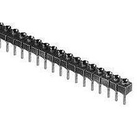
13 PIN INLINE HEADER
Manufacturer
Aries Electronics
Series
0513r
Type
SIPr
Datasheet
1.25-0513-10.pdf
(1 pages)
Specifications of 13-0513-10
Number Of Positions Or Pins (grid)
13 (1 x 13)
Pitch
0.100" (2.54mm)
Mounting Type
Through Hole
Features
Closed Frame
Contact Finish
Gold
Contact Finish Thickness
10µin (0.25µm)
Number Of Rows
1
Number Of Positions / Contacts
13
Contact Plating
Gold/Tin
Termination Style
Solder Tail
Lead Free Status / RoHS Status
Lead free / RoHS Compliant
Other names
Q977175
FEATURES:
• Rows of socket strips may be mounted on any centers and are
• Available with solder tail or wire wrap pins. Consult Dat a Sheet
• ”Break” feature allows strips to be cut to the number of positions
SPECIFICATIONS:
• Body material is black UL 94V-0 Glass-filled 4/6 Nylon.
• Pin body is Brass Alloy 360 1/2 hard per UNS C36000 ASTM-
• Pin body plating is either 10 μ [.25μm] min. Gold per MIL-G-
• 4-fingered collet contact is Beryllium Copper Alloy per UNS
• Contact plating is either 200 μ [5.08μm] min. 93/7 Tin/Lead per
• Contact current rating=3 Amps.
• Insertion Force=180 grams/pin; Withdrawal Force=90
• Operating temperature=221°F [105°C] Tin & Tin/Lead plating
• Insertion Force=180 grams/pin; Withdrawal
• Accepts leads .015-.025 [.38-.64] in dia., .100-.146
MOUNTING CONSIDERATIONS:
•Suggested PCB hole size=.030 ± .002 [.76 ± .05] dia.
end-to-end or side-by-side stackable for .100 [2.54] grid or
matrix patterns.
No. 12014 for wire wrap pins.
desired.
B16-00.
45204 or 200μ [5.08μm] min. 93/7 Tin/Lead per ASTM B545 or
200μ [5.08μm] min. Tin per ASTM B545 Type 1 over 100μ
[2.54μm] min. Nickel per SAE-AMS-QQ-N-290.
C17200 ASTM-B194-01.
ASTM B545 or 200μ [5.08μm] min Tin per ASTM B545 Type 1
or 10μ [.25μm] Gold per MIL-G-45204 over 50 μ min. [1.27μm]
Nickel per SAE-AMS-QQ-N-290. Heavy 30 μ [.76μm] Gold
Plating also available.
grams/pin; Normal Force=140 grams/pin; based on a .018 [.46]
dia. test lead.
Force=90 grams/pin; Normal Force=140 grams/pin; based on a
.018 [.46] dia. test lead.
[2.54-3.71] long.
PRINTOUTS OF THIS DOCUMENT MAY BE OUT OF DATE AND SHOULD BE CONSIDERED UNCONTROLLED
unless otherwise specified
All tolerances ± .005 [.13]
http://www.arieselec.com • info@arieselec.com
Series 0513 Pin-Line Collet Sockets
with Solder Tail Pins
=257°F [125°C] Gold plating.
A
LL DIMENSIONS
Bristol, PA USA
TEL: (215) 781-9956
FAX: (215) 781-9845
:
INCHES
[
MILLIMETERS
No. of pins:
Note: Aries specializes in custom design and production. In addition to the
standard products shown on this page, special materials, platings, sizes, and
configurations can be furnished, depending on quantities. Aries reserves the
right to change product specifications without notice.
1 to 25
Plating:
0=Gold collet/Tin shell
0TL= Gold collet/Tin/Lead Shell
1=Gold collet/Gold shell
“A”=NO. OF PINS PER ROW X .100 [2.54]
“B”=(NO. OF PINS PER ROW - 1) X .100 [2.54]
ORDERING INFORMATION
]
Solder tail pin
X X - 0 5 1 3 - 1 X X X X
Pin-Line collet sockets
CONTACT DETAIL
abc
Consult Data Sheet
also available with
Series
wire wrap pins.
No. 12014.
Optional suffix:
H=Heavy Gold on
T=Tin collet/Tin shell
TL=Tin/Lead collet/
Tin/Lead shell
collet
REV. E
12013
Related parts for 13-0513-10
Image
Part Number
Description
Manufacturer
Datasheet
Request
R

Part Number:
Description:
IC & Component Sockets PIN LINE COLLET SCKT SOLDER TAIL 13 PINS
Manufacturer:
Aries Electronics
Datasheet:
Part Number:
Description:
IC & Component Sockets PIN LINE COLLET SCKT SOLDER TAIL 13 PINS
Manufacturer:
Aries Electronics
Datasheet:
Part Number:
Description:
IC & Component Sockets PIN LINE COLLET SCKT SOLDER TAIL 13 PINS
Manufacturer:
Aries Electronics
Datasheet:
Part Number:
Description:
IC & Component Sockets PIN LINE COLLET SCKT SOLDER TAIL 13 PINS
Manufacturer:
Aries Electronics
Datasheet:

Part Number:
Description:
13 MODII HDR SRST SHRD .100CL
Manufacturer:
TE Connectivity
Datasheet:

Part Number:
Description:
Row-to-Row DIP Adapter Socket
Manufacturer:
ARIES [Aries Electronics, Inc.]
Datasheet:
Part Number:
Description:
5-Pin PLCC Motorola MC68HC11E9-to-56-Pin SDIP Adapter
Manufacturer:
ARIES [Aries Electronics, Inc.]
Datasheet:
Part Number:
Description:
64-Pin DIP-to-PLCC 68-Pin Zilog Z80180 Adapter
Manufacturer:
ARIES [Aries Electronics, Inc.]
Datasheet:
Part Number:
Description:
RoHs/WEEE-Compliant SOIC-to-JEDEC TO Adapter
Manufacturer:
ARIES [Aries Electronics, Inc.]
Datasheet:
Part Number:
Description:
68-Pin PLCC-to-DIP 64-Pin Motorola MC68HC000 Adapter
Manufacturer:
ARIES [Aries Electronics, Inc.]
Datasheet:
Part Number:
Description:
Surface Mount-to-DIP JEDEC SOT-25, SOT-23A-6 Adapter
Manufacturer:
ARIES [Aries Electronics, Inc.]
Datasheet:
Part Number:
Description:
0.5mm 8- and 10-Pin
Manufacturer:
ARIES [Aries Electronics, Inc.]
Datasheet:
Part Number:
Description:
24-Pin SOWIC-to-22-Pin
Manufacturer:
ARIES [Aries Electronics, Inc.]
Datasheet:
Part Number:
Description:
ZIF PGA Test & Burn-in Socket for Any Footprint on Std 13x13 to 21x21 Grid
Manufacturer:
ARIES [Aries Electronics, Inc.]
Datasheet:
