E6248 QUANTUM ATMEL, E6248 Datasheet - Page 11
E6248
Manufacturer Part Number
E6248
Description
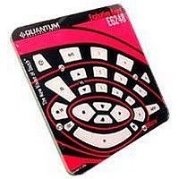
QT60248 24 Key Matrix Panel Qtouch Evaluation Kit
Manufacturer
QUANTUM ATMEL
Datasheet
1.E6248.pdf
(15 pages)
Specifications of E6248
Silicon Manufacturer
Atmel
Application Sub Type
Touch Sensor
Kit Application Type
Sensing - Touch / Proximity
Silicon Core Number
QT60168 QT60248


SPI Direct Port (J5)
Header J5 gives access to all the signals useful for communicating with the chip. The pinout of the
connector is described below:
Line Sync (J5, pin 9)
External Noise Sync: Feed a TTL or 5V CMOS synchronization pulse into pin 9 of J5 with respect to
GND.
Acquisition bursts can be synchronized to an external source of repetitive electrical noise (such as
50Hz or 60Hz) using the Noise Sync feature which can be enabled in QmBtn (View Key Settings
Global Settings). External repetitive signals are thereby heavily suppressed since the system and the
noise become synchronized and no longer beat or alias with respect to each other. The sync input
triggers the burst for key 0 (X0Y0); the device waits for the sync signal for up to 100 ms after the end
of a preceding full matrix scan (after key #23); then, when a sync pulse is received, the matrix is
scanned once in its entirety. If no sync pulse is received in 100ms, the part wakes on its own and re-
scans the matrix once, then goes back to sleep. Sync pulses should be spaced no more than 99ms
apart to prevent this from happening.
Oscilloscope Sync (SSYNC)
The SSYNC test point can be used to synchronize an oscilloscope. When enabled in QmBtn, this
signal provides a pulse that brackets the chosen burst or bursts, making diagnostics much simpler.
With the scope sync enabled for one key, the X matrix drive signals can be clearly seen.
LK12..LK15
These four links provide a simple way to convert 5Volts logic levels to 3.3Volts logic levels. If the host
runs at 3.3Volts, these 4 links should be disconnected (using a blade). If the host is running at 5 Volts
they should be left connected.
Pin
Name
GND
1
+5V
2
BOARD DETAILS
+3.3V
3
/DRDY
4
/SS
5
MOSI
6
MISO
7
SCK
8
Line Sync
9
11
RST
10
Related parts for E6248
Image
Part Number
Description
Manufacturer
Datasheet
Request
R

Part Number:
Description:
QT60486 And QT60326 Qtouch Evalution Kit
Manufacturer:
QUANTUM ATMEL
Datasheet:

Part Number:
Description:
EVALUATION KIT, MATRIX, 16/24 KEY
Manufacturer:
QUANTUM ATMEL
Datasheet:

Part Number:
Description:
IC SENSOR QTOUCH 4CHAN 20SSOP
Manufacturer:
Atmel
Datasheet:

Part Number:
Description:
QPROX SENSOR 24 KEYS, SMD, MLF-32
Manufacturer:
QUANTUM ATMEL
Datasheet:

Part Number:
Description:
KIT EVAL FOR AT42QT2160-MMU
Manufacturer:
Atmel
Datasheet:

Part Number:
Description:
KIT EVAL FOR AT42QT1060-MMU
Manufacturer:
Atmel
Datasheet:

Part Number:
Description:
KIT EVALUATION FOR AT42QT1040
Manufacturer:
Atmel
Datasheet:

Part Number:
Description:
KIT EVAL FOR QT100
Manufacturer:
Atmel
Datasheet:

Part Number:
Description:
EVAL BOARD FOR QT1103
Manufacturer:
Atmel
Datasheet:

Part Number:
Description:
BOARD EVALUATION FOR QT300
Manufacturer:
Atmel
Datasheet:
Part Number:
Description:
KIT EVAL/DEV USING QT102-ISG
Manufacturer:
Atmel
Datasheet:
Part Number:
Description:
KIT EVAL/DEV USING QT1081-ISG
Manufacturer:
Atmel
Datasheet:
Part Number:
Description:
QPROX SENSOR 24 KEYS, SMD, MLF-32
Manufacturer:
QUANTUM ATMEL
Datasheet:

Part Number:
Description:
IC, 16, 24 KEY QMATRIX SENSOR, TQFP-32
Manufacturer:
QUANTUM ATMEL
Datasheet:
Part Number:
Description:
QPROX SENSOR 16 KEYS, SMD, MLF-32
Manufacturer:
QUANTUM ATMEL
Datasheet: