EVAL-ADXL326Z Analog Devices Inc, EVAL-ADXL326Z Datasheet - Page 11
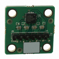
EVAL-ADXL326Z
Manufacturer Part Number
EVAL-ADXL326Z
Description
Accelerometer Eval. Board
Manufacturer
Analog Devices Inc
Series
iMEMS®r
Specifications of EVAL-ADXL326Z
Silicon Manufacturer
Analog Devices
Application Sub Type
Accelerometer - Three-Axis
Kit Application Type
Sensing - Motion / Vibration / Shock
Silicon Core Number
ADXL326
Sensor Type
Accelerometer, 3 Axis
Sensing Range
±19g
Interface
Analog
Sensitivity
57mV/g
Voltage - Supply
1.8 V ~ 3.6 V
Embedded
No
Utilized Ic / Part
ADXL326
Lead Free Status / RoHS Status
Lead free / RoHS Compliant
Available stocks
Company
Part Number
Manufacturer
Quantity
Price
Company:

Part Number:
EVAL-ADXL326Z
Manufacturer:
Analog Devices Inc
Quantity:
135


APPLICATIONS INFORMATION
POWER SUPPLY DECOUPLING
For most applications, a single 0.1 μF capacitor, C
close to the ADXL326 supply pins adequately decouples the
accelerometer from noise on the power supply. However, in
applications where noise is present at the 50 kHz internal clock
frequency (or any harmonic thereof), additional care in power
supply bypassing is required because this noise can cause errors
in acceleration measurement. If additional decoupling is needed, a
100 Ω (or smaller) resistor or ferrite bead can be inserted in the
supply line. Additionally, a larger bulk bypass capacitor (1 μF or
greater) can be added in parallel to C
from the ADXL326 ground to the power supply ground is low
impedance because noise transmitted through ground has a
similar effect as noise transmitted through V
SETTING THE BANDWIDTH USING C
The ADXL326 has provisions for band limiting the X
Z
low-pass filtering for antialiasing and noise reduction. The 3 dB
bandwidth equation is
or more simply
The tolerance of the internal resistor (R
much as ±15% of its nominal value (32 kΩ), and the bandwidth
varies accordingly. A minimum capacitance of 0.0047 μF for C
C
Table 4. Filter Capacitor Selection, C
Bandwidth (Hz)
1
10
50
100
200
500
SELF TEST
The ST pin controls the self test feature. When this pin is set to
V
The resulting movement of the beam allows the user to test
whether the accelerometer is functional. The typical change in
output is −1.08 g (corresponding to −62 mV) in the X axis, +1.08 g
(+62 mV) on the Y axis, and +1.83 g (+105 mV) on the Z axis.
This ST pin can be left open circuit or connected to common
(COM) in normal use.
Never expose the ST pin to voltages greater than V
this cannot be guaranteed due to the system design (for instance,
there are multiple supply voltages), then a low V
diode between ST and V
OUT
Y
S
, an electrostatic force is exerted on the accelerometer beam.
, and C
f
f
pins. Capacitors must be added at these pins to implement
−3 dB
–3 dB
= 1/(2π(32 kΩ) × C
= 5 μF/C
Z
is recommended in all cases.
(X, Y, Z)
S
is recommended.
(X, Y, Z)
)
DC
Capacitor (μF)
4.7
0.47
0.10
0.05
0.027
0.01
. Ensure that the connection
X
FILT
, C
) typically varies as
Y
, and C
S
.
X
, C
F
DC
Y
clamping
OUT
, AND C
S
Z
, placed
+ 0.3 V. If
, Y
OUT
, and
Z
Rev. 0 | Page 11 of 16
X
,
DESIGN TRADE-OFFS FOR SELECTING FILTER
CHARACTERISTICS: THE NOISE/BW TRADE-OFF
The selected accelerometer bandwidth ultimately determines
the measurement resolution (smallest detectable acceleration).
Filtering can be used to lower the noise floor to improve the
resolution of the accelerometer. Resolution is dependent on the
analog filter bandwidth at X
The output of the ADXL326 has a typical bandwidth greater
than 500 Hz. The user must filter the signal at this point to limit
aliasing errors. The analog bandwidth must be no more than half
the analog-to-digital sampling frequency to minimize aliasing.
The analog bandwidth can be further decreased to reduce noise
and improve resolution.
The ADXL326 noise has the characteristics of white Gaussian
noise, which contributes equally at all frequencies and is described
in terms of μg/√Hz (the noise is proportional to the square root
of the accelerometer bandwidth). The user should limit bandwidth
to the lowest frequency needed by the application to maximize
the resolution and dynamic range of the accelerometer.
With the single-pole roll-off characteristic, the typical noise of
the ADXL326 is determined by
Often, the peak value of the noise is desired. Peak-to-peak noise
can only be estimated by statistical methods. Table 5 is useful for
estimating the probabilities of exceeding various peak values, given
the rms value.
Table 5. Estimation of Peak-to-Peak Noise
Peak-to-Peak Value
2 × rms
4 × rms
6 × rms
8 × rms
USE WITH OPERATING VOLTAGES OTHER THAN 3 V
The ADXL326 is tested and specified at V
powered with V
performance parameters change as the supply voltage is varied.
The ADXL326 output is ratiometric; therefore, the output
sensitivity (or scale factor) varies proportionally to the supply
voltage. At V
At V
The zero g bias output is also ratiometric; therefore, the zero g
output is nominally equal to V
The output noise is not ratiometric but is absolute in volts;
therefore, the noise density decreases as the supply voltage
increases. This is because the scale factor (mV/g) increases while
the noise voltage remains constant. At V
axis noise density is typically 120 μg/√Hz, while at V
X- and Y-axis noise density is typically 270 μg/√Hz.
rms Noise = Noise Density ×
S
= 2 V, the output sensitivity is typically 38 mV/g.
S
= 3.6 V, the output sensitivity is typically 68 mV/g.
S
as low as 1.8 V or as high as 3.6 V. Note that some
% of Time That Noise Exceeds
Nominal Peak-to-Peak Value
32
4.6
0.27
0.006
OUT
S
, Y
/2 at all supply voltages.
(
OUT
BW
, and Z
S
×
S
= 3 V; however, it can be
1.6
= 3.6 V, the X- and Y-
OUT
)
.
ADXL326
S
= 2 V, the
Related parts for EVAL-ADXL326Z
Image
Part Number
Description
Manufacturer
Datasheet
Request
R

Part Number:
Description:
ENERCHIP CC EVAL KIT
Manufacturer:
Cymbet Corporation
Datasheet:

Part Number:
Description:
BOARD EVAL FOR AD976
Manufacturer:
Analog Devices Inc
Datasheet:

Part Number:
Description:
BOARD EVAL FOR ADXL345
Manufacturer:
Analog Devices Inc
Datasheet:

Part Number:
Description:
ENERCHIP CC SEH EVAL KIT
Manufacturer:
Cymbet Corporation
Datasheet:

Part Number:
Description:
ENERCHIP EP ENERGY HARVEST EVAL
Manufacturer:
Cymbet Corporation
Datasheet:

Part Number:
Description:
EVAL BOARD FOR TW6864-LB2-GR
Manufacturer:
Intersil
Datasheet:
Part Number:
Description:
EVAL BOARD FOR TW8816-LB3-GR
Manufacturer:
Intersil
Datasheet:
Part Number:
Description:
EVAL BOARD FOR TW8817-TA3-GRS
Manufacturer:
Intersil
Datasheet:

Part Number:
Description:
EVALUATION MODULE FOR ADUM4160
Manufacturer:
Analog Devices Inc
Datasheet:

Part Number:
Description:
BOARD EVALUATION ADCMP581BCP
Manufacturer:
Analog Devices Inc
Datasheet:
Part Number:
Description:
BOARD EVALUATION ADM1041
Manufacturer:
Analog Devices Inc
Datasheet:

Part Number:
Description:
EVAL BOARD FOR STM32F107VCT
Manufacturer:
STMicroelectronics
Datasheet:
Part Number:
Description:
BOARD EVAL FOR AD1954
Manufacturer:
Analog Devices Inc
Datasheet:
Part Number:
Description:
BOARD EVAL FOR AD1955
Manufacturer:
Analog Devices Inc
Datasheet:

Part Number:
Description:
BOARD EVAL FOR AD7655
Manufacturer:
Analog Devices Inc
Datasheet: