2-141 Cinch Connectors, 2-141 Datasheet - Page 235
2-141
Manufacturer Part Number
2-141
Description
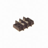
CONN BARRIER BLOCK .438" 2 POS
Manufacturer
Cinch Connectors
Series
141r
Type
Wire to Boardr
Specifications of 2-141
Terminal Block Type
Barrier Block
Number Of Circuits
2
Number Of Positions
4
Pitch
0.438" (11.12mm)
Number Of Rows
2
Current
20A
Voltage
250V
Wire Gauge
14 AWG
Mounting Type
Chassis Mount or Panel Mount
Top Termination
Screws
Bottom Termination
Closed
Barrier Type
2 Wall (Dual)
Features
Flange
Color
Black
Operating Temperature
-55°F ~ 300°F
Material - Insulation
Phenol Formaldehyde (Phenolic)
Material Flammability Rating
UL94 V-1
Product
Barrier Terminal Blocks
Number Of Positions / Contacts
2
Current Rating
20 A
Voltage Rating
250 V
Wire Gauge Max (awg)
14
Current, Rating
20 A (Max.)
Length
1.187 in.
Material, Block
Brass
Material, Screw
Steel
Mounting Style
Bottom
Plating, Screw
Nickel over Copper Flash
Screw Size
6-32 x 1⁄4
Temperature Range
-55 to +300 °F
Lead Free Status / RoHS Status
Lead free / RoHS Compliant
Lead Free Status / RoHS Status
Lead free / RoHS Compliant, Lead free / RoHS Compliant
Other names
2-141-P
2141-P
CBB202
2141-P
CBB202
Available stocks
Company
Part Number
Manufacturer
Quantity
Price
Company:

Part Number:
2-1411573-1
Manufacturer:
TE
Quantity:
40 500
Company:
Part Number:
2-1411573-1
Manufacturer:
TE
Quantity:
396 694
Company:
Part Number:
2-1414987-3
Manufacturer:
TE
Quantity:
10 000
Company:
Part Number:
2-1415038-1
Manufacturer:
TE
Quantity:
20 000
Company:
Part Number:
2-1415538-2
Manufacturer:
TE
Quantity:
6 000


6
.085 in. (2.16mm)
Density
Miniature Ribbon
Mounting Options
Various mounting options are available with Cinch Miniature Ribbon
and SUPERIBBON products:
•
Standard Panel Cutout Recommendations
Dimensions
•
•
Size
Size
14
24
36
50
14
24
36
50
64
Through-Hole/Threaded Hole -- These products require separate hardware to mount
the connector to a panel or other component. Versions are available to accommodate
#3, #4, and in some cases, through #8 hardware.
Standard size cutouts are adequate for mounting panel-mount connectors to system
panels with this type of hardware. They may be front- or rear-mounted. (Sockets with
bail latches, however, must be front-mounted unless a modified cutout is used to clear
the latch retaining hardware.)
Metal Shell PC Mount products are available in some versions with standoffs to the
printed circuit board. These may be conductive or insulated.
Panel Clips -- These devices are add-on accessories for All-Plastic products and are
available as optional configurations on certain Metal Shell products. They allow you to
mount the connector to the system panel without screws, nuts, or spacers, and leave
the connector’s mounting holes free for use in latching, if so desired.
Boardlocks -- These devices, found on certain solder-tail PC mount products, fasten the
connector to the printed circuit board with solder as part of the wave soldering process.
Thus, there is no additional labor required to complete the assembly, and a cost savings
can often be realized.
1.417 (35.99) 1.098 (27.89)
1.842 (46.79) 1.523 (38.68) 1.365 (34.67) .580 (14.73)
2.352 (59.74) 2.033 (51.64) 1.875 (47.63) .580 (14.73)
2.947 (74.85) 2.628 (66.75) 2.472 (62.79) .580 (14.73)
1.417 (35.99) 1.172 (29.77)
1.842 (46.79) 1.597 (40.56) 1.212 (30.78) .610 (15.49)
2.352 (59.74) 2.107 (53.52) 1.722 (43.74) .610 (15.49)
2.947 (74.85) 2.703 (68.66) 2.317 (58.85) .610 (15.49)
3.592 (91.24) 3.298 (83.77) 2.912 (73.96) .610 (15.49)
Call Toll Free: 1 (800) 323-9612
A
A
SUPERIBBON, Plug or Socket
Plug or Fixed-Mount Socket
B
B
.940 (23.88) .580 (14.73)
.787 (19.99) .610 (15.49)
C
C
Rear Mounting
D
D
Introduction
6-4
1.417 (35.99) 1.153 (29.29)
1.842 (46.79) 1.578 (40.08) 1.420 (36.07)
2.352 (59.74) 2.088 (53.04) 1.930 (49.02)
2.947 (74.85) 2.683 (68.15) 2.525 (64.14)
A
Front Mounting
Float-Mount Socket
B
.995 (25.27) .635 (16.13)
C
.635 (16.13)
.635 (16.13)
.635 (16.13)
D
Related parts for 2-141
Image
Part Number
Description
Manufacturer
Datasheet
Request
R

Part Number:
Description:
CONN BARRIER BLOCK .375" 2 POS
Manufacturer:
Cinch Connectors
Datasheet:

Part Number:
Description:
CONN BARRIER BLOCK .563" 2 POS
Manufacturer:
Cinch Connectors
Datasheet:

Part Number:
Description:
CONN BARRIER BLOCK .375" 2 POS
Manufacturer:
Cinch Connectors
Datasheet:
