7-141 Cinch Connectors, 7-141 Datasheet - Page 134
7-141
Manufacturer Part Number
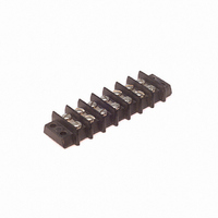
7-141
Description
BARRIER BLOCK 7POS .438"
Manufacturer
Cinch Connectors
Series
141r
Type
Wire to Boardr
Specifications of 7-141
Terminal Block Type
Barrier Block
Number Of Circuits
7
Number Of Positions
14
Pitch
0.438" (11.12mm)
Number Of Rows
2
Current
20A
Voltage
250V
Wire Gauge
14 AWG
Mounting Type
Chassis Mount or Panel Mount
Top Termination
Screws
Bottom Termination
Closed
Barrier Type
2 Wall (Dual)
Features
Flange
Color
Black
Operating Temperature
-55°F ~ 300°F
Material - Insulation
Phenol Formaldehyde (Phenolic)
Material Flammability Rating
UL94 V-1
Product
Barrier Terminal Blocks
Number Of Positions / Contacts
7
Current Rating
20 A
Voltage Rating
250 V
Wire Gauge Max (awg)
14
Lead Free Status / RoHS Status
Lead free / RoHS Compliant
Lead Free Status / RoHS Status
Lead free / RoHS Compliant, Lead free / RoHS Compliant
Other names
7-141-P
7141-P
CBB207
7141-P
CBB207
Available stocks
Company
Part Number
Manufacturer
Quantity
Price

Company:
Part Number:
7-1414995-5
Manufacturer:
AMPTYCO
Quantity:
353
Company:
Part Number:
7-1415006-1
Manufacturer:
TE
Quantity:
1 001
Part Number:
7-1415006-1
Manufacturer:
TE/泰科
Quantity:
20 000
Company:
Part Number:
7-1415036-1
Manufacturer:
TE
Quantity:
37 102
Company:
Part Number:
7-1415036-1
Manufacturer:
TE
Quantity:
35 000
Company:
Part Number:
7-1415525-1
Manufacturer:
TE
Quantity:
5 000


D-subminiature Metal Shell
Solder Cup, Vertical PCB Mount, and Wire Wrap
Basic D Series
Insulator Material: Glass-filled polyester (white), UL 94V-O rated
Connector Shell: Steel with zinc plating and yellow chromate
4-40 Clinch Nut: Steel with cadmium plating and yellow
Dual Float Bushing: Stainless steel, passivated
Operating Temperature: -65°C to + 125°C
Shock: 50G peak per MIL-STD-202, Method 213, Condition G
Vibration: 12 cycles in three perpendicular directions @
Moisture Resistance: 90-95% relative humidity @ 40°C for 96
Individual Contact Insertion and
Durability: 500 mating cycles
Call Toll Free: 1 (800) 323-9612
Insulation Resistance:
Separation Force (minimum/maximum): 0.7 oz./12 oz.
Withstanding Voltage:
Offered in Wire Wrap and Solder Cup styles for wire termination and vertical style for
PCB mount.
Offered with .120 mounting holes, 4-40 clinch nuts, and dual float bushings.
Offered in 9, 15, 25, 37, and 50 position plugs and sockets.
Available with gold flash or 30µin. gold plating.
Approvals:
• UL Recognized - Files E170218 (UL1977) and E130965 (UL1863).
• CSA Approved - File LR31996.
See pages 4-5 thru 4-10 for standard dimensions, contact arrangements, and panel
mounting specifications.
Contact Resistance:
Current Rating:
10-2000Hz, per MIL-STD-202, Method 204,
Condition D
chromate finish
finish or tin plating (grounding indents on plug)
hours per MIL-STD-202, Method 103
Minimum 1250V RMS @ sea level
5 Amps
2.7 milliohms maximum
5000 megohms maximum (initial);
1000 megohms (minimum) after
environmental testing
4-40
Related parts for 7-141
Image
Part Number
Description
Manufacturer
Datasheet
Request
R

Part Number:
Description:
BARRIER BLOCK 7POS .375"
Manufacturer:
Cinch Connectors
Datasheet:

Part Number:
Description:
BARRIER BLOCK 7POS .563"
Manufacturer:
Cinch Connectors
Datasheet:

Part Number:
Description:
CONN BARRIER BLOCK .375" 7 POS
Manufacturer:
Cinch Connectors
Datasheet:
