20-141 Cinch Connectors, 20-141 Datasheet
20-141
Specifications of 20-141


Related parts for 20-141


20-141 Summary of contents
Page 1
COMMERCIAL Barrier Blocks Circular Mini DIN BNC Jones Plugs Edge Connectors ...
Page 2
... Density Commercial Solder Cup/Wire D-Microminiature] Cinch Commercial Products, consisting of Jones Plugs and Sockets, Barrier Blocks, Edge Cards, Two-Piece Commercial Dins, Mini Din Plugs, and their newest addition the 75Ω Press-Fit BNC Receptacle, provide a wide variety of connectors for the purchaser and designer to chose from ...
Page 3
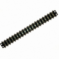
Barrier Blocks ■ Interposing barriers between terminals yield higher electrical ratings and provide additional protection against frayed wire shorting. ■ A wide variety of barrier blocks makes it possible to select the combination of mechanical and electrical characteristics that best ...
Page 4
... Single 5-40 Max. Max. Current Wire Watts/ Voltage Rating Size Terminal 250 Volts 15 Amps #16 3750 250 Volts 20 Amps #14 5000 250 Volts 30 Amps #10 7500 250 Volts 40 Amps #10 10,000 250 Volts 50 Amps #8 12,500 250 Volts 70 Amps #6 54,000 250 Volts ...
Page 5
... Dim. 1.032 1.407 1.782 2.157 2.532 2.907 3.282 3.657 4.032 4.407 4.782 5.157 5.532 5.907 6.282 6.657 7.032 7.407 7.782 8.157 8.532 8.907 9 ...
Page 6
... Solder Terminals can be ordered separately. Terminal Type “Y” “3/4W” “W” .375 Density, 5-40 x 3/16" BH Screw, Open Bottom, Double Row “3/4W” Terminals Catalog No. 1-140-Y 1-140-3/4W 2-140-Y 2-140-3/4W 3-140-Y 3-140-3/4W 4-140-Y 4-140-3/4W 5-140-Y 5-140-3/4W 6-140-Y 6-140-3/4W 7-140-Y 7-140-3/4W 8-140-Y ...
Page 7
... Use Standard Marker Strips for “3/4W” and “W” Solder Terminals. Accessories • Jumpers • Fanning Strips Call Toll Free: 1 (800) 323-9612 .375 Density, 5-40 x 3/16" BH Screw, Open Bottom, Double Row Catalog No. Catalog No. MS-1-140 MS-1-140-Y MS-2-140 MS-2-140-Y MS-3-140 MS-3-140-Y MS-4-140 ...
Page 8
... Dim. 1.187 1.625 2.062 2.500 2.938 3.375 3.812 4.250 4.687 5.125 5.562 6.000 6.437 6.875 7.312 7 ...
Page 9
... Catalog No. Y-141 3/4W-141 W-141 Call Toll Free: 1 (800) 323-9612 2-9 Marketed exclusively through distribution. ...
Page 10
... MS-3-141 MS-3-141-Y MS-4-141 MS-4-141-Y MS-5-141 MS-5-141-Y MS-6-141 MS-6-141-Y MS-7-141 MS-7-141-Y MS-8-141 MS-8-141-Y MS-9-141 MS-9-141-Y MS-10-141 MS-10-141-Y MS-11-141 MS-11-141-Y MS-12-141 MS-12-141-Y MS-13-141 MS-13-141-Y MS-14-141 MS-14-141-Y MS-15-141 MS-15-141-Y MS-16-141 MS-16-141-Y MS-17-141 MS-17-141-Y MS-18-141 MS-18-141-Y MS-19-141 MS-19-141-Y MS-20-141 MS-20-141-Y 2-10 Marketed exclusively through distribution. ...
Page 11
... Dim. 1.531 2.094 2.656 3.219 3.781 4.344 4.906 5.468 6.031 6.594 7.156 7.719 8.281 8.844 9.406 9.969 10.531 Marketed exclusively through distribution. ...
Page 12
... Barrier Blocks Series 142 Solder Terminal Options Dimensions “Y” Terminals Ordering Information No. of Terminals Catalog No 10-142-Y 11 11-142-Y 12 12-142-Y 13 13-142-Y 14 14-142-Y 15 15-142-Y 16 16-142-Y 17 17-142-Y Solder Terminals can be ordered separately. Terminal Type “Y” “3/4W” “W” .563 Density, 8-32 x 5/16" ...
Page 13
... Terminals Use Standard Marker Strips for “3/4W” and “W” Solder Terminals. Accessories • Jumpers • Fanning Strips Call Toll Free: 1 (800) 323-9612 .563 Density, 8-32 x 5/16" BH Screw, Open Bottom, Double Row Catalog No. Catalog No. MS-1-142 MS-1-142-Y MS-2-142 MS-2-142-Y MS-3-142 MS-3-142-Y ...
Page 14
... Series 150 Double Row Electrical Characteristics Voltage Rating: 250 VAC RMS maximum Current Rating: 40 Amps maximum Maximum Watts Per Terminal: 10,000 Mechanical Characteristics Maximum Wire Size: #10 AWG Recommended Tightening Torque: 20 lb.-in. Dimensions Ordering Information No. of Standard Screw Terminals Catalog No. 1 1-150 ...
Page 15
... Density, 10-32 x 5/16" BH Screw, Open Bottom, Double Row Catalog No. Catalog No. MS-1-150 MS-1-150-Y MS-2-150 MS-2-150-Y MS-3-150 MS-3-150-Y MS-4-150 MS-4-150-Y MS-5-150 MS-5-150-Y MS-6-150 MS-6-150-Y MS-7-150 MS-7-150-Y MS-8-150 MS-8-150-Y MS-9-150 MS-9-150-Y MS-10-150 MS-10-150-Y Marketed exclusively through distribution. 2-17 “Y” Terminal Call Toll Free: 1 (800) 323-9612 ...
Page 16
... Density, 12-32 x 3/8" BH Screw, Open Bottom, Double Row “M” Dim. (in) 1.750 2.625 3.500 4.375 5.250 6.125 7.000 7.875 Catalog No. W-151 2-18 “L” Marker Strip Dim. (in) Catalog No. 2.282 N/A 3.157 MS-2-151 4.032 MS-3-151 4.907 MS-4-151 5.782 MS-5-151 6.657 MS-6-151 7 ...
Page 17
... Accessories None Available for 152 Series. 1.25 Density, 1/4-28 x 1/2" BH Screw, Open Bottom, Double Row “M” “L” Dim. (in) Dim. (in) 2.250 2.876 3.375 4.001 4.500 5.126 5.625 6.251 6.750 7.376 7.875 8.501 Marketed exclusively through distribution. ...
Page 18
... Dim. (in) 1.032 1.407 1.782 2.157 2.532 2.907 3.282 3.657 4.032 4.407 4.782 5.157 5.532 5.907 6.282 6.657 7.032 7.407 7 ...
Page 19
... Ordering Information No. of Terminals .375 Density, 6-32 x 1/4" BH Screw, Open Bottom, Double Row “3/4W” Terminals Catalog No. Catalog No. 1-164-Y 1-164-3/4W 2-164-Y 2-164-3/4W 3-164-Y 3-164-3/4W 4-164-Y 4-164-3/4W 5-164-Y 5-164-3/4W 6-164-Y 6-164-3/4W 7-164-Y 7-164-3/4W 8-164-Y 8-164-3/4W 9-164-Y 9-164-3/4W 10-164-Y 10-164-3/4W 11-164-Y 11-164-3/4W 12-164-Y 12-164-3/4W ...
Page 20
... Use Standard Marker Strips for “3/4W” and “W” Solder Terminals. Call Toll Free: 1 (800) 323-9612 [.050” (1.27mm) Density .375 Density, 6-32 x 1/4" Solder Cup/Wire BH Screw, Open Bottom, D-Microminiature] Double Row “Y” Terminal Catalog No. Catalog No. N/A N/A MS-2-140 ...
Page 21
... MSX-10-540 4.782 MSX-11-540 5.157 MSX-12-540 5.532 MSX-13-540 5.907 MSX-14-540 6.282 MSX-15-540 6.657 MSX-16-540 7.032 MSX-17-540 7.407 MSX-18-540 7.782 MSX-19-540 8.157 MSX-20-540 8.532 MSX-21-540 8.907 MSX-22-540 9.282 MSX-23-540 9.657 MSX-24-540 10.032 MSX-25-540 10.407 MSX-26-540 10.782 MSX-27-540 11.157 MSX-28-540 11.532 MSX-29-540 11.907 MSX-30-540 12 ...
Page 22
... Barrier Blocks Series 541 Electrical Characteristics Voltage Rating: 600 Volts maximum Current Rating: 20 Amps Maximum Watts Per Terminal: 5000 Mechanical Characteristics Maximum Wire Size: #14 Recommended Tightening Torque: 12 lb.-in. Dimensions Ordering Information No. of Terminals Catalog No. 2 2-541 3 3-541 4 4-541 5 5-541 6 6-541 7 7-541 ...
Page 23
... Marker Strip Dim. (in) Catalog No. 2.095 MSX-2-542 2.658 MSX-3-542 3.221 MSX-4-542 3.784 MSX-5-542 4.347 MSX-6-542 4.910 MSX-7-542 5.473 MSX-8-542 6.036 MSX-9-542 6 ...
Page 24
... Dimension 1.469 1.844 2.219 2.594 2.969 3.344 3.719 4.094 4.469 “L” .719 Marketed exclusively through distribution. Call Toll Free: 1 (800) 323-9612 ...
Page 25
... .063 1.60 .146 3.71 .094 .078 1.98 .152 3.86 .125 .094 2.39 .177 4.50 .125 Marketed exclusively through distribution 2.39 3.18 3. 2.31 2.62 3. 2.39 3.18 3.18 ...
Page 26
Barrier Blocks Accessories Quick Clamp Terminals Simplifies engaging of wires to barrier blocks. Wire is inserted into flared opening and screw is tightened. Screws are brass binder head type with nickel plating. Terminals are brass with tin plating. Includes two ...
Page 27
... Minimize wiring errors. ■ Available in straight and right-angle styles. ■ Available with cable clamp hole on right or left side, designated by “L” or “R” at end of catalog number. ■ Cable clamp hole for securing cable/wires with lacing twine or ty-wrap. Insulation Material: UL 94HB rated XPC, chocolate ...
Page 28
... Marketed exclusively through distribution. 2-31 Catalog No. 2-160B-L 3-160B-L 4-160B-L 5-160B-L 6-160B-L 7-160B-L 8-160B-L 9-160B-L 10-160B-L 11-160B-L 12-160B-L 13-160B-L 14-160B-L 15-160B-L 16-160B-L 17-160B-L 18-160B-L 19-160B-L 20-160B-L 21-160B-L Call Toll Free: 1 (800) 323-9612 ...
Page 29
... Catalog No. 2-160A-L 3-160A-L 4-160A-L 5-160A-L 6-160A-L 7-160A-L 8-160A-L 9-160A-L 10-160A-L 11-160A-L 12-160A-L 13-160A-L 14-160A-L 15-160A-L 16-160A-L 17-160A-L 18-160A-L 19-160A-L 20-160A-L 21-160A-L Marketed exclusively through distribution. ...
Page 30
... Fanning Strips Dimensions Catalog No. 5-161-R Dimensions Catalog No. 5-161A-R Call Toll Free: 1 (800) 323-9612 2-33 2 Marketed exclusively through distribution. ...
Page 31
Barrier Block Accessories Catalog Numbers and Dimensions for Fanning Strips for 142 Series Barrier Blocks Straight Type Ordering Information No. of Terminals Catalog No. 2 2-162-R 3 3-162-R 4 4-162-R 5 5-162-R 6 6-162-R 7 7-162-R 8 8-162-R 9 9-162-R ...
Page 32
Barrier Block Accessories Materials Insulation Material rated XPC, chocolate Contact Material: Steel Contact Plating: Cadmium Mechanical Characteristics Mounting Hole: .140" (3.56mm) diameter Strip Dimension: .0625" (1.59mm) thick x .375" (9.53mm) wide Lug Density: .375" (9.53mm) Ordering Information ...
Page 33
Jones Plugs/Sockets Series 300 ■ Solder lug terminals with .093" x .062" (2.36mm x 1.57mm) wiring holes. ■ Two-contact "Jones" connector is round, all others are rectangular. ■ For use in cable-to-panel and cable-to-cable applications. ■ Designed for light and ...
Page 34
Jones Plugs/Sockets Series 300 Polarizing Patterns - 300 Series Multiple Density Solder Eyelet Marketed exclusively through distribution. Call Toll Free: 1 (800) 323-9612 2-37 ...
Page 35
... .625 15.88 .469 11 ...
Page 36
... NOTE: 15-position plug and socket require only two mounting brackets, mounted on center of connector. [.050” (1.27mm) Density Multiple Density Solder Cup/Wire Solder Eyelet With Angle D-Microminiature] Bracket/Less Angle Bracket No. of Catalog No. Contacts 2 P-302-LAB 3 ...
Page 37
... Panel Cutout Dimensions Reference 303-FP 304-FP 306-FP 308-FP 310-FP 312-FP Call Toll Free: 1 (800) 323-9612 [.050” (1.27mm) Density Multiple Density Solder Cup/Wire Solder Eyelet D-Microminiature] Flush Plate Catalog No. Socket S-302-FP S-303-FP S-304-FP S-306-FP N/A N/A N length of plug contacts ...
Page 38
... Jones [.050” (1.27mm) Density Plugs/Sockets Solder Cup/Wire Series 300 D-Microminiature] 300 Series with End Brackets (EB) No. of Catalog No. Catalog No. Contacts Plug 15 P-315-EB 18 P-318-EB 21 P-321-EB 24 P-324-EB 28 P-328-EB 30 P-330-EB 33 P-333-EB NOTE: Not available in contact sizes 2-12. Dimensions No ± .031 (.79mm) Contacts 15 2.313 58. ...
Page 39
Jones DURA-CON ® Plugs/Sockets High Reliability Series 300 All-Plastic 300 Series with Recessed Plate (RP) No. of Catalog No. Contacts Plug 2 P-302-RP 3 P-303-RP 4 P-304-RP 6 P-306- N/A 10 P-310-RP 12 P-312-RP NOTE: Not available in ...
Page 40
... Jones [.050” (1.27mm) Density Plugs/Sockets Solder Cup/Wire Series 300 D-Microminiature] 300 Series with Shallow Bracket (SB) No. of Catalog No. Catalog No. Contacts Plug 15 P-315-SB S-315-SB 18 P-318-SB S-318-SB 21 P-321-SB S-321-SB 24 P-324-SB S-324-SB 27 P-327-SB S-327-SB 30 P-330-SB S-330-SB 33 P-333-SB S-333-SB NOTE: Not available in contact sizes 2-12. ...
Page 41
... Call Toll Free: 1 (800) 323-9612 [.050” (1.27mm) Density Multiple Density Solder Cup/Wire Solder Eyelet D-Microminiature] Deep Bracket Catalog No. Socket S-302-DB S-303-DB S-304-DB S-306-DB N/A N/A N/A ...
Page 42
... Jones [.050” (1.27mm) Density Plugs/Sockets Solder Cup/Wire Series 300 D-Microminiature] 300 Series with Hood and 90° Cable Clamp (CCE) No. of Catalog No. Catalog No. Contacts Plug 2 P-302-CCE S-302-CCE 3 P-303-CCE S-303-CCE 4 P-304-CCE S-304-CCE 6 P-306-CCE S-306-CCE 8 N/A 10 P-310-CCE 12 P-312-CCE 15 P-315-CCE S-315-CCE 18 P-318-CCE S-318-CCE 21 P-321-CCE ...
Page 43
... No. of Contacts Call Toll Free: 1 (800) 323-9612 [.050” (1.27mm) Density Multiple Density Solder Cup/Wire Solder Eyelet With Hood & 180° Clamp D-Microminiature] Catalog No. Socket S-302-CCT S-303-CCT S-304-CCT S-306-CCT N/A N/A N/A S-315-CCT S-318-CCT S-321-CCT ...
Page 44
... Jones [.050” (1.27mm) Density Plugs/Sockets Solder Cup/Wire Series 300 D-Microminiature] 300 Series Plug with Hood and Lock (CCT-L) and Socket with Hood and Keeper (CCT-K) No. of Catalog No. Catalog No. Contacts Plug w/ Lock Socket w/ Keeper 2 P-302-CCT-L S-302-CCT-K 3 P-303-CCT-L S-303-CCT-K 4 P-304-CCT-L S-304-CCT-K 6 P-306-CCT-L ...
Page 45
... These are recommended configurations. • * These are possible configurations, but not normally recommended. NOTE: Cinch layout S315-12 is available only in “AB” or “LAB”. Replacement Drive Pins for Series 300 Plugs and Sockets with Cable Caps and Clamps Dimensions Dim ...
Page 46
Jones Plugs/Sockets Series 2400 ■ For use in cable-to-cable and cable-to-panel applications. ■ Designed for medium duty. ■ Plug prongs are .250" (6.35mm) wide and .055" (1.40mm) thick. ■ Socket contacts have solder eyelet contacts of .093" diameters. ■ Polarized ...
Page 47
Jones Plugs/Sockets Series 2400 2400 Series Less Angle Bracket No. of Catalog No. Catalog No. Contacts Plug 2 N/A S-2402-LAB 4 P-2404-LAB S-2404-LAB 6 P-2406-LAB S-2406-LAB 8 P-2408-LAB S-2408-LAB 10 P-2410-LAB S-2410-LAB 12 P-2412-LAB S-2412-LAB Plug Dimensions - Plug or ...
Page 48
... Panel Cutout dimensions are on page 2-61. Call Toll Free: 1 (800) 323-9612 [.050” (1.27mm) Density Multiple Density Solder Cup/Wire Solder Eyelet D-Microminiature] With Angle Bracket Catalog No. Socket S-2402-AB S-2404-AB S-2406-AB S-2408-AB S-2410-AB S-2412-AB Socket ...
Page 49
... Panel Cutout dimensions are on page 2-61. [.050” (1.27mm) Density Multiple Density Solder Cup/Wire Solder Eyelet D-Microminiature] Shallow Bracket Catalog No. Socket S-2402-SB S-2404-SB S-2406-SB S-2408-SB S-2410-SB S-2412- 1.062 26.99 1 ...
Page 50
... Panel Cutout dimensions are on page 2-61. Call Toll Free: 1 (800) 323-9612 [.050” (1.27mm) Density Multiple Density Solder Cup/Wire Solder Eyelet D-Microminiature] Deep Bracket Catalog No. Socket S-2402-DB S-2404-DB S-2406-DB S-2408-DB S-2410-DB S-2412-DB Socket ...
Page 51
... Jones [.050” (1.27mm) Density Plugs/Sockets Solder Cup/Wire Series 2400 D-Microminiature] 2400 Series with Hood and 90° Clamp No. of Catalog No. Catalog No. Contacts Plug 2 N/A S-2402-CCE 4 P-2404-CCE S-2404-CCE 6 P-2406-CCE S-2406-CCE 8 P-2408-CCE S-2408-CCE 10 P-2410-CCE S-2410-CCE 12 P-2412-CCE S-2412-CCE Dimensions - Plug or Socket No Contacts .625 15. ...
Page 52
DURA-CON Jones ® Plugs/Sockets High Reliability Series 2400 All-Plastic 2400 Series with Hood and 180° Clamp No. of Catalog No. Contacts Plug 2 N/A 4 P-2404-CCT 6 P-2406-CCT 8 P-2408-CCT 2 10 P-2410-CCT 12 P-2412-CCT Plug Socket Dimensions - Plug ...
Page 53
... P-2404-DB S-2404-DB 1.750 44.46 P-2406-DB S-2406-DB 2.188 55.56 P-2408-DB S-2408-DB 2.624 66.68 P-2410-DB P-2410-DB 3.062 77.80 P-2412-DB S-2412-DB 3.500 88.90 [.050” (1.27mm) Density Solder Cup/Wire Panel Cutout Dimensions D-Microminiature 1.008 25.60 1.015 25.78 1.445 36.70 1.015 25.78 1.886 47 ...
Page 54
... Operating Temperature: -40°C to +70°C Heat Resistance: 196 hrs. at 100°C Salt Spray: MIL-STD-202, Method 101D, Condition D Vibration: MIL-STD-202, Method 204, Condition B Humidity: MIL-STD-202, Method 103, 48 hrs. at 90-95 40°C Voltage Rating: 500 VAC RMS, 707 VDC Current Rating: 1 Amp at 100 VAC ...
Page 55
... The above cable assemblies are recommended where greater contact durability is required. Additional Capabilities • Additional lengths or colors of the above cable assemblies can be produced. Consult factory for custom orders. • Custom-plated contacts can be provided. Consult factory for information. Single-Ended Cable Assembly 5-Contact ...
Page 56
Circular Mini DIN Plugs ■ Individual components available for cable assembly with overmolding. ■ Plug insulator available with contact positions and 8. ■ Seamless shield case is crimped to cable shield; designed to meet FCC ...
Page 57
... Prepare multi-conductor cable. • Crimp contacts onto individual conductors using tool MDT-P25 or tool MDT-P35. • Insert contact with conductor into insulator using tool MDT-P41 or have insertion tool MDT-P28 with insulator locating vice MDT-P29. • Insert insulator into the shield case using tool MDT-P34 or MDT-P30. ...
Page 58
... Dip solder tails on .200" (5.08mm) row centers double readout. ■ Bifurcated semi-bellows contacts for added contact reliability. ■ Ideal for applications involving vibration or board irregularities. ■ Contact positions: 12, 15, 18, 20, 22, 25, 28, 30, 31, 36, 37, 40, 43, 44, 49, 50, 52, 60, 70, AT, and XT. ■ Accepts .062" (1.59mm) thick PC boards. ...
Page 59
... 60.96 2.600 66.04 2.760 70.10 68.58 2.900 73.66 3.060 77.72 73.66 3.100 78.74 3.260 82.80 76.20 3.200 81.28 3.360 85.34 76.20 3.200 81.28 3.360 85.34 88.90 3.700 93.98 3.860 98.04 91.44 3.800 96.52 3.960 100.58 99.06 4.100 104.14 4.260 108.20 106.68 4 ...
Page 60
... Commercial ■ Dip solder tails single readout and double readout on .140" (3.56mm) row centers or .200" (5.08mm) row centers. ■ Solder eyelet, single readout and double readout on .200" (5.08mm) row centers. ■ Available with unique tails for PC board retention; holds the connector firmly on the board during wave soldering operations. ■ ...
Page 61
... Dip solder tails, double readout, .200" (5.08mm) row spacing, .156" (3.96mm) long 6/12 50-12SN-3 50-12SN-1 10/20 50-20SN-3 50-20SN-1 12/24 50-24SN-3 50-24SN-1 15/30 50-30SN-3 50-30SN-1 18/36 50-36SN-3 ...
Page 62
... Dip solder tails, single readout, .156" (3.96mm) long or .234" (5.94mm) long. ■ Dip solder tails, double readout, .156" (3.96mm) or .234" (5.94mm) long on .200" (5.08mm) row spacing, or .125" (3.18mm) long on .140" (3.56mm) row spacing. ■ Solder eyelet, single readout and double readout on .200" (5.08mm) row spacing. ...
Page 63
... 1.785 45.34 2.410 61.21 2.723 69.16 3.191 81.05 3.660 92.96 3.973 100.91 4.285 108.84 4.754 120.75 Marketed exclusively through distribution. Call Toll Free: 1 (800) 323-9612 Call Toll Free: 1 (800) 323-9612 ...
Page 64
... Double Readout .128" (3.25mm) Mounting Hole Solder Eyelet Dip Solder Tails No. of .234" (5.94mm) Long Pos./Cont. .200" (5.08mm) Between .200" (5.08mm) Between .140" (3.56mm) Between .140" (3.56mm) Between Row Spacing Catalog No. Catalog No. 6/12 50-12H-30 50-12S-20 10/20 50-20H-30 50-20S-20 ...
Page 65
... Contact Plating: 30µin. select gold over 50µin. nickel in the contact areas, 10µin. gold tails Shock: Per MIL-STD-202E, Method 213, Condition C Operating Temperature: -65°C to +125°C Vibration: Per MIL-STD-202E, Method 204, Condition B Humidity: Per MIL-STD-202E, Method 103, Condition B Withstanding Voltage: Current Rating: Contact Resistance: Insulation Resistance: Individual Contact Insertion and Separation Force: 16 oz. maximum with .070" ...
Page 66
... Catalog No. 50-12S-30 50-20S-30 50-24S-30 50-30S-30 50-36S-30 50-44S-30 50-50S-30 2- 1.785 45.33 2.410 61.21 2.723 69.16 3.191 81.05 3.660 92.96 4.285 108.83 4.754 120.75 Marketed exclusively through distribution. Call Toll Free: 1 (800) 323-9612 ...
Page 67
Edge Connector Accessories Card Guides Card guide for .100" (2.54mm) and .156" (3.96mm) density edge connectors. Accepts .062" (1.59mm) thick PC boards. Card guides attach to mounting ears and guide printed circuit board into connector. Order separately. Material: Polypropylene Part ...
Page 68
... Cup Diameter in mm Catalog No. .406 10.32 41A .500 12.70 41B .656 16.67 41C .797 20.24 41D .938 23.81 41E 1.062 26.99 41F 1.156 29.37 41G 1.438 36.51 41H 1.156 29.37 41V ...
Page 69
... Impedance. ■ Meets Lucent Technologies (AT&T) Requirements. Body: One-piece diecast zinc per QQ-Z-363 Plating: Nickel, 150µin. min. per QQ-N-290 over copper, 200µin. min. per MIL-C-14550 Center Contact: Beryllium copper Plating: Gold, 30µin. minimum over nickel, 50µin. minimum ...
Page 70
Press-Fit BNC Coaxial Connector Board Mount Receptacle for 75 Ω Ω Applications Production Insertion Tool Design Press-Fit BNC Connector Dimensions Ordering Information Catalog Number: BNC-1-PF Standard Package: Anti-Static Tube, 48 Connectors Per Tube Call Toll Free: 1 (800) 323-9612 2-77 ...