17-142 Cinch Connectors, 17-142 Datasheet - Page 60
17-142
Manufacturer Part Number
17-142
Description
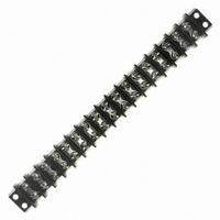
CONN BARRIER BLOCK .563" 17 POS
Manufacturer
Cinch Connectors
Series
142r
Datasheet
1.140J-1.pdf
(70 pages)
Specifications of 17-142
Terminal Block Type
Barrier Block
Number Of Circuits
17
Number Of Positions
34
Pitch
0.563" (14.30mm)
Number Of Rows
2
Current
30A
Voltage
250V
Wire Gauge
10 AWG
Mounting Type
Chassis Mount or Panel Mount
Top Termination
Screws
Bottom Termination
Closed
Barrier Type
2 Wall (Dual)
Features
Flange
Color
Black
Operating Temperature
-55°F ~ 300°F
Material - Insulation
Phenol Formaldehyde (Phenolic)
Material Flammability Rating
UL94 V-1
Rohs Compliant
Yes
Lead Free Status / RoHS Status
Lead free / RoHS Compliant
Other names
CBB434


CARDCON
Edge Connector
Commercial
Insulation Material: UL 94V-0 rated glass-filled polyester, black
Contact Material: Spring brass
Contact Plating: 10µ" selective gold over 30µ" nickel in contact
Shock: Per MIL-STD-202E, Method 213, Condition C
Operating Temperature: -65°C to +105°C
Vibration: Per MIL-STD-202E, Method 204, Condition B
Humidity: Per MIL-STD-202, Method 103, Condition B
Accessories:
Polarizing Key: Two types (order separately):
a) for between-contact polarization and
b) for in-contact polarization
See page 2-72 for more information.
Card Guide Posts: (order separately):
Attach to mounting ears and guide PC board into connector
See page 2-72 for more information.
Individual Contact Insertion and Separation Force:
Call Toll Free: 1 (800) 323-9612
■ Dip solder tails single readout and double readout on .140" (3.56mm) row
■ Solder eyelet, single readout and double readout on .200" (5.08mm)
■ Available with unique tails for PC board retention; holds the connector
■ Bifurcated semi-bellows contacts for added contact reliability.
■ Ideal for applications involving vibration or board irregularities.
■ Contact positions: 6, 10, 12, 15, 18, 22, 24, and 25.
■ Accepts single- or double-sided .062" (1.59mm) thick PC boards.
■ Available less mounting ears or with .128" (3.25mm) mounting hole.
■ Meets applicable performance criteria of MIL-C-21097.
■ UL Recognized - file E170218 (UL1977) E130965 (UL1863).
centers or .200" (5.08mm) row centers.
row centers.
firmly on the board during wave soldering operations.
16 oz. maximum with .070" (1.78mm) blade;
1 oz. minimum with .054" (1.37mm) blade
Insulation Resistance:
Withstanding Voltage:
Contact Resistance:
™
Current Rating:
area, tin on tails
1800 VAC RMS (@ sea level)
5 Amps
6 Milliohms maximum
5000 Megohms minimum
.156" (3.96mm) Density
Dip Solder/Solder Eyelet
2-64
Marketed exclusively through distribution.
Related parts for 17-142
Image
Part Number
Description
Manufacturer
Datasheet
Request
R

Part Number:
Description:
CONN BARRIER BLOCK .438" 17 POS
Manufacturer:
Cinch Connectors
Datasheet:

Part Number:
Description:
CONN BARRIER BLOCK .375" 17 POS
Manufacturer:
Cinch Connectors
Datasheet:

Part Number:
Description:
CONN BARRIER BLOCK .375" 17 POS
Manufacturer:
Cinch Connectors
Datasheet:

Part Number:
Description:
TERMINAL BLOCK JUMPER TYPE F
Manufacturer:
Cinch Connectors
Datasheet:

Part Number:
Description:
D-Subminiature Connectors MCHNED PIN 20-24AWG
Manufacturer:
Cinch Connectors
Datasheet:
Part Number:
Description:
Terminal Block,4 Contacts,0.44 Pitch
Manufacturer:
Cinch Connectors
Datasheet:

Part Number:
Description:
Terminal Block,8 Contacts,0.375 Pitch
Manufacturer:
Cinch Connectors
Datasheet: