131-6403-101 JOHNSON/EMERSON, 131-6403-101 Datasheet - Page 2
131-6403-101
Manufacturer Part Number
131-6403-101
Description
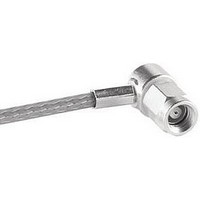
RF/COAXIAL SMB PLUG R/A 50OHM CRIMP/SLDR
Manufacturer
JOHNSON/EMERSON
Datasheet
1.131-6403-101.pdf
(2 pages)
Specifications of 131-6403-101
Body Style
Right Angle Plug
Coaxial Termination
Solder / Crimp
Rg Cable Type
RG-161, 174, 188, 316
Contact Material
Brass
Contact Plating
Gold
Connector Type
SMB Coaxial
Impedance
50ohm
Lead Free Status / RoHS Status
Lead free / RoHS Compliant


SMC - 50 Ohm Connectors
Specifications
Impedence: 50 ohms
Frequency Range: 0-10 GHz
VSWR: (f = GHz)
RG-178 cable ................................... 1.25 + .04f
RG-316 and .086 semi-rigid
Uncabled receptacles ............................ N/A
Adapters ........................................... 1.20 + .04f
Working Voltage: (Vrms maximum)†
Connectors for Cable Type
Dielectric Withstanding Voltage: (VRMS minimum at sea level)†
Corona Level: (Volts minimum at 70,000 feet)†
Insertion Loss: (dB maximum, tested at 4 GHz)
Insulation Resistance: 1000 megohms minimum
Contact Resistance: (milliohms maximum)
Center contact (straight cabled
Center contact (right angle cabled
Outer contact (gold plated connectors) ................. 1.0
Outer contact (nickel plated connectors) .............. 2.5
Braid to body (gold plated connectors) ................. 1.0
Braid to body (nickel plated connectors) ............... 2.5
RF Leakage: (dB minimum tested at 2.5 GHz)
Avoid user injury due to misapplication. See safety advisory definitions inside front cover.
Johnson Components
** All gold plated parts inlcude a .00005" min. nickel underplate barrier layer.
cable ............................................. 1.20 + .04f
RG-178 ............................................... 250
RG-316, .086 semi-rigid
Connectors for RG-178 ........................................................................... 750
Connectors for RG-316, .086 semi-rigid
Connectors for RG-178 ........................................................................... 185
Connectors for RG-316, .086 semi-rigid .................................................. 250
Uncabled receptacles and adapters ........................................................ N/A
Straight cable connectors .................................................................. 0.25 dB
Right angle cable connectors ............................................................ 0.50 dB
Uncabled receptacles and adapters ........................................................ N/A
connectors and uncabled receptacles) .............. 6.0
Cable connectors ............................................................................... -55 dB
Uncabled receptacles and adapters ........................................................ N/A
connectors and adapters) ................................ 12.0
uncabled receptacles, adapters ........ 335
uncabled receptacles, adapters ........................................................... 1000
TM
• P.O. Box 1732 • Waseca, MN 56093-0832 • 1-800-247-8256 • Fax: 507-833-6287 • www.johnsoncomponents.com
ELECTRICAL RATINGS
PLUG
Straight Cabled
Sea Level
MATING ENGAGEMENT FOR SMC SERIES PER MIL-C-39012
Initial
Right Angle Cabled
1.40 + .06f
1.30 + .04f
70K Feet
60
85
Environmental
After
16.0
N/A
N/A
N/A
N/A
8.0
JACK
RF High Potential Withstanding Voltage: (Vrms minimum, tested at
Engagement Design: MIL-C-39012, Series SMC
Engagement/Disengagment Force: 16 inch-ounce maximum torque
Mating Torque: 35 to 50 inch-ounce
Coupling Proof Torque: 100 inch-ounce minimum
Coupling Nut Retention: 35 pounds minimum
Contact Retention: 4 lbs. minimum axial force (captivated contacts)
Cable Retention:
Connectors for RG-178 ...................................... 10
Connectors for RG-316 ...................................... 20
Connectors for .086 semi-rigid ........................... 30
* or cable breaking strength whichever is less
Durability: 500 cycles minimum
Temperature Range: - 65 C to + 165 C
Thermal Shock: MIL-STD-202, Method 107, Condition B
Corrosion: MIL-STD-202, Method 101, Condition B
Shock: MIL-STD-210, Method 213, Condition C
Vibration: MIL-STD-202, Method 204, Condition D
MATERIAL SPECIFICATIONS
Bodies: Brass per QQ-B-626, gold plated** per MIL-G-45204 .00001" min or
Contacts: Male - brass per QQ-B-626, gold plated per MIL-G-45204
Nut Retention Spring: Beryllium copper per QQ-C-533, unplated
Insulators: PTFE fluorocarbon per ASTM D 1710 and ASTM D 1457
Expansion Caps: Brass per QQ-B-613, gold plated per MIL-G-45204 .00001"
Crimp Sleeves: Copper per WW-T-799, gold plated per MIL-G-45204 .00001"
Mounting Hardware: Brass (nuts) per QQ-B-626 or phosphor bronze
ENVIRONMENTAL RATINGS (Meets or exceed the applicable paragraph of
4 and 7 MHz)†
Connectors for RG-178 ........................................................................... 500
Connectors for RG-316 ........................................................................... 700
Uncabled receptacles and adapters ........................................................ 600
.00003" min.
Female - beryllium copper per QQ-C-530, gold plated per MIL-G-45204
nickel plated per QQ-N-290
.00003" min.
min. or nickel plated per QQ-N-290
min. or nickel plated per QQ-N-290
(lockwashers) per QQ-B-750, gold plated per MIL-G-45204 .00001" min. or
nickel plated per QQ-N-290
1 inch-ounce minimum torque (uncabled receptacles)
MECHANICAL RATINGS
NOTES
1. Inside of contact to meet VSWR, mating charac-
MIL-C-39012
teristics and connector durability when mated with
a dia .019/.021 (0.48/0.53) male contact.
INCHES (MILLIMETERS)
CUSTOMER DRAWINGS AVAILABLE UPON REQUEST
PLUG
Axial Force*
(pounds)
Torque
(in-oz)
N/A
N/A
16
JACK
Related parts for 131-6403-101
Image
Part Number
Description
Manufacturer
Datasheet
Request
R


Part Number:
Description:
FPGA - Field Programmable Gate Array 21K LUTs 131 I/O S Series DSP 1.2V -6 I
Manufacturer:
Lattice
Part Number:
Description:
FPGA - Field Programmable Gate Array 12K LUTs 131 I/O DSP 1.2V -6 Spd I
Manufacturer:
Lattice
Part Number:
Description:
FPGA - Field Programmable Gate Array 21K LUTs 131 I/O DSP 1.2V -6 I
Manufacturer:
Lattice
Part Number:
Description:
FPGA - Field Programmable Gate Array 21K LUTs 131 I/O DSP 1.2V -6
Manufacturer:
Lattice