4-142 Cinch Connectors, 4-142 Datasheet
4-142
Specifications of 4-142
4142-P
CBB304


Related parts for 4-142


4-142 Summary of contents
Page 1
Catalog No. C-865 ...
Page 2
CIN::APSE High Speed Interconnect Technology ® ...
Page 3
CIN::APSE ® High-Speed Interconnect Technology High signal speed capability enabling frequencies greater than 20 GHz. Z-Axis, solderless, compression mount interconnect system. Applications include production Land Grid Array (LGA) integrated circuit sockets, flex circuit to PCB, and parallel PCB to PCB ...
Page 4
... It is constructed of randomly wound molybdenum wire that is formed into a cyclindrical shape. Standard CIN::APSE contact diameters are 0.020" and 0.040". Mechanical • Small form factor (0.020" diameter by 0.32" min. high) • Low compression force (approx. 2.5 oz. min. per contact) • ...
Page 5
CIN::APSE ® High-Speed Interconnect Technology 1 TYPICAL CONFIGURATION 1. Button-Only This is the basic CIN::APSE contact configuration ideally suited for z-axis applications requiring minimum height, high density, and signal integrity. This configuration is used in LGA and IC ...
Page 6
... CIN::APSE ® High-Speed Interconnect Technology VARIOUS CIN::APSE APPLICATIONS IC Component to Board Socket (LGA) Hybrid Circuit to Flex to PCB Cable to PCB/Flex PCB to PCB LCD to Flex to PCB Flex Circuit to PCB Call Toll Free: 1 (800) 323-9612 1-4 1 ...
Page 7
COMMERCIAL Barrier Blocks Circular Mini DIN BNC Jones Plugs Edge Connectors ...
Page 8
... The Jones Plugs and Sockets have been utilized for decades and provide a quick, reliable, and economical means of solving your higher current-carrying capacity needs. Available in two series (300 and 2,400), these connectors can be found in data processing controls; amusement and vending machines; medical, communication, and test equipment; as well as industrial controls and heavy-duty, battery-powered equipment ...
Page 9
... Plating - Nickel Screws: Material - Steel Plating - Nickel over copper flash Solder Terminals: Material - Brass Plating - Electro-Tin Marker Strip Material: Nema Grade XPC, UL Rated 94V-O Operating Temperature: -55° to +300°F Certifications: UL Recognized - File E61245 CSA - LR 31996 Call Toll Free: 1 (800) 323-9612 Marketed exclusively through distribution. ...
Page 10
... Current Wire Watts/ Voltage Rating Size Terminal 250 Volts 15 Amps #16 3750 250 Volts 20 Amps #14 5000 250 Volts 30 Amps #10 7500 250 Volts 40 Amps #10 10,000 250 Volts 50 Amps #8 12,500 250 Volts 70 Amps #6 54,000 250 Volts 15 Amps #14 3750 600 Volts 15 Amps #16 3750 600 Volts ...
Page 11
... Maximum Watts Per Terminal: 3750 Mechanical Characteristics Maximum Wire Size: #16 AWG Recommended Tightening Torque: 9 lb.-in. Dimensions Ordering Information No. of Terminals Call Toll Free: 1 (800) 323-9612 .375 Density, 5-40 x 3/16" BH Screw, Open Bottom, Double Row Standard Screw “M” Catalog No. Dim. 1 1-140 ...
Page 12
... Solder Terminals can be ordered separately. Terminal Type “Y” “3/4W” “W” .375 Density, 5-40 x 3/16" BH Screw, Open Bottom, Double Row “3/4W” Terminals Catalog No. 1-140-Y 1-140-3/4W 2-140-Y 2-140-3/4W 3-140-Y 3-140-3/4W 4-140-Y 4-140-3/4W 5-140-Y 5-140-3/4W 6-140-Y 6-140-3/4W 7-140-Y 7-140-3/4W 8-140-Y ...
Page 13
... Use Standard Marker Strips for “3/4W” and “W” Solder Terminals. Accessories • Jumpers • Fanning Strips Call Toll Free: 1 (800) 323-9612 .375 Density, 5-40 x 3/16" BH Screw, Open Bottom, Double Row Catalog No. Catalog No. MS-1-140 MS-1-140-Y MS-2-140 MS-2-140-Y MS-3-140 MS-3-140-Y MS-4-140 ...
Page 14
... Barrier Blocks Series 141 Electrical Characteristics Voltage Rating: 250 VAC RMS maximum Current Rating: 20 Amps maximum Maximum Watts Per Terminal: 5000 Mechanical Characteristics Maximum Wire Size: #14 AWG Recommended Tightening Torque: 12 lb.-in. Dimensions Ordering Information No. of Terminals Call Toll Free: 1 (800) 323-9612 .438 Density, 6-32 x 1/4" ...
Page 15
... Solder Terminals can be ordered separately. Terminal Type “Y” “3/4W” “W” .438 Density, 6-32 x 1/4" BH Screw, Open Bottom, Double Row “3/4W” Terminals “W” Terminals Catalog No. Catalog No. 1-141-3/4W 1-141-W 2-141-3/4W 2-141-W 3-141-3/4W 3-141-W 4-141-3/4W ...
Page 16
... Use Standard Marker Strip for “3/4W” and “W” Solder Terminals. Accessories • Jumpers • Fanning Strips Call Toll Free: 1 (800) 323-9612 .438 Density, 6-32 x 1/4" BH Screw, Open Bottom, Double Row “Y” Terminal Catalog No. Catalog No. MS-1-141 MS-1-141-Y MS-2-141 MS-2-141-Y ...
Page 17
... Dim. 1.531 2.094 2.656 3.219 3.781 4.344 4.906 5.468 6.031 6 ...
Page 18
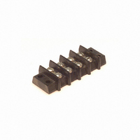
... Catalog No. Y-142 3/4W-142 W-142 2-13 “W” Terminals Catalog No. 1-142-W 2-142-W 3-142-W 4-142-W 5-142-W 6-142-W 7-142-W 8-142-W 9-142-W 10-142-W 11-142-W 12-142-W 13-142-W 14-142-W 15-142-W 16-142-W 17-142-W Marketed exclusively through distribution. Call Toll Free: 1 (800) 323-9612 ...
Page 19
... MS-1-142-Y MS-2-142 MS-2-142-Y MS-3-142 MS-3-142-Y MS-4-142 MS-4-142-Y MS-5-142 MS-5-142-Y MS-6-142 MS-6-142-Y MS-7-142 MS-7-142-Y MS-8-142 MS-8-142-Y MS-9-142 MS-9-142-Y MS-10-142 MS-10-142-Y MS-11-142 MS-11-142-Y MS-12-142 MS-12-142-Y MS-13-142 MS-13-142-Y MS-14-142 MS-14-142-Y MS-15-142 MS-15-142-Y MS-16-142 MS-16-142-Y MS-17-142 MS-17-142-Y 2-14 “Y” Terminal Marketed exclusively through distribution. ...
Page 20
... Density, 10-32 x 5/16" Barrier Blocks BH Screw, Open Bottom, Series 150 Double Row Electrical Characteristics Voltage Rating: 250 VAC RMS maximum Current Rating: 40 Amps maximum Maximum Watts Per Terminal: 10,000 Mechanical Characteristics Maximum Wire Size: #10 AWG Recommended Tightening Torque: 20 lb.-in. Dimensions Ordering Information No ...
Page 21
... Accessories None Available for 150 Series. .688 Density, 10-32 x 5/16" BH Screw, Open Bottom, Double Row Catalog No. Catalog No. MS-1-150 MS-1-150-Y MS-2-150 MS-2-150-Y MS-3-150 MS-3-150-Y MS-4-150 MS-4-150-Y MS-5-150 MS-5-150-Y MS-6-150 MS-6-150-Y MS-7-150 MS-7-150-Y MS-8-150 MS-8-150-Y MS-9-150 MS-9-150-Y MS-10-150 MS-10-150-Y Marketed exclusively through distribution. ...
Page 22
... Barrier Blocks Series 151 Electrical Characteristics Voltage Rating: 250 Volts maximum Current Rating: 50 Amps maximum Maximum Watts Per Terminal: 12,500 Mechanical Characteristics Maximum Wire Size: #8 Recommended Tightening Torque: 40 lb.-in. Dimensions Ordering Information No. of Terminals Catalog No. 1 1-151 2 2-151 3 3-151 4 4-151 5 5-151 ...
Page 23
... Barrier Blocks Series 152 Electrical Characteristics Voltage Rating: 250 Volts maximum Current Rating: 70 Amps maximum Maximum Watts Per Terminal: 54,000 Mechanical Characteristics Maximum Wire Size: #6 Recommended Tightening Torque: 75 lb.-in. Dimensions Ordering Information No. of Terminals Catalog No. 1 1-152 2 2-152 3 3-152 4 4-152 5 5-152 ...
Page 24
... Barrier Blocks Series 164 Electrical Characteristics Voltage Rating: 250 Volts maximum Current Rating: 15 Amps maximum Maximum Watts Per Terminal: 3750 Mechanical Characteristics Maximum Wire Size: #14 Recommended Tightening Torque: 12 lb.-in. Dimensions Ordering Information No. of Terminals Call Toll Free: 1 (800) 323-9612 .375 Density, 6-32 x 5/16" ...
Page 25
... Terminals Ordering Information No. of Terminals .375 Density, 6-32 x 1/4" BH Screw, Open Bottom, Double Row “3/4W” Terminals Catalog No. Catalog No. 1-164-Y 1-164-3/4W 2-164-Y 2-164-3/4W 3-164-Y 3-164-3/4W 4-164-Y 4-164-3/4W 5-164-Y 5-164-3/4W 6-164-Y 6-164-3/4W 7-164-Y 7-164-3/4W 8-164-Y 8-164-3/4W 9-164-Y 9-164-3/4W 10-164-Y 10-164-3/4W ...
Page 26
... Use Standard Marker Strips for “3/4W” and “W” Solder Terminals. Call Toll Free: 1 (800) 323-9612 [.050” (1.27mm) Density .375 Density, 6-32 x 1/4" Solder Cup/Wire BH Screw, Open Bottom, D-Microminiature] Double Row “Y” Terminal Catalog No. Catalog No. N/A N/A MS-2-140 ...
Page 27
... Call Toll Free: 1 (800) 323-9612 .375 Density, 5-40 x 1/4" BH Screw, Closed Bottom, Double Row “M” Catalog No. Dim. (in) 2-540 1.125 3-540 1.500 4-540 1.875 5-540 2.250 6-540 2.625 7-540 3.000 8-540 3.375 9-540 3.750 10-540 4.125 11-540 4.500 12-540 4.875 13-540 5 ...
Page 28
... Density, 6-32 x 1/4" BH Screw, Closed Bottom, Double Row “M” “L” Dim. (in) Dim. (in) 1.314 1.626 1.752 2.064 2.190 2.502 2.628 2.940 3.066 3.378 3.504 3.816 3.942 4.254 4.380 4 ...
Page 29
... Barrier Blocks Series 542 Electrical Characteristics Voltage Rating: 600 Volts maximum Current Rating: 30 Amps Maximum Watts Per Terminal: 7500 Mechanical Characteristics Maximum Wire Size: #10 Recommended Tightening Torque: 16 lb.-in. Dimensions Ordering Information No. of Terminals Catalog No 10-542 11 11-542 12 12-542 13 13-542 14 14-542 15 15-542 16 16-542 ...
Page 30
... Density, 5-40 x 3/16" BH Screw, Dip Solder, Single Row Catalog No. “M” .184 Tail Lgth Dimension 2-176-3 1.125 3-176-3 1.500 4-176-3 1.875 5-176-3 2.250 6-176-3 2.625 7-176-3 3.000 8-176-3 3.375 9-176-3 3 ...
Page 31
... Barrier Blocks High Reliability Accessories All-Plastic Solder Terminals 3/4W, Y, and W Optional Terminals for use with Cinch terminal blocks. See chart for type and dimensions. (Below) 2 Ordering Information "3/4 W" Terminals - Dimensions Catalog A Number in mm 3/4W-140 .953 24.21 3/4W-141 1.156 29.36 3/4W-142 1 ...
Page 32
... Ordering Information Barrier Block Series Type Catalog No. 140 A 140J-1 141 B 141J-1 141 F 141J 142 F 95B 142, 542 D 142J-1* 142, 542 E 142J-2 540 C 540J 541 C 541J 542 C 542J * Connects two alternate terminals Screw Wire Gauge Size Range AWG 12 thru 22 10 thru 16 Type A ...
Page 33
... Available with cable clamp hole on right or left side, designated by “L” or “R” at end of catalog number. Cable clamp hole for securing cable/wires with lacing twine or ty-wrap. Insulation Material: UL 94HB rated XPC, chocolate Contact Material: Brass Contact Plating: Cadmium Call Toll Free: 1 (800) 323-9612 ...
Page 34
... Barrier Block Accessories Catalog Numbers and Dimensions for Fanning Strips for 140 Series Terminal Blocks Straight Type Dimensions Catalog No. 6-160-R Ordering Information No. of Terminals Catalog No. 2 2-160-R 3 3-160-R 4 4-160-R 5 5-160-R 6 6-160-R 7 7-160-R 8 8-160-R 9 9-160-R 10 10-160-R 11 11-160-R 12 12-160-R 13 13-160-R 14 14-160-R 15 15-160-R 16 16-160-R ...
Page 35
... DURA-CON ® Barrier Block High Reliability Accessories All-Plastic Catalog Numbers and Dimensions for Fanning Strips for 140 Series Terminal Blocks, Continued Right-Angle Type Dimensions 2 Ordering Information Call Toll Free: 1 (800) 323-9612 Fanning Strips Fanning Strips Catalog No. 6-160A-R No. of Terminals Catalog No. ...
Page 36
... Barrier Block Accessories Catalog Numbers and Dimensions for Fanning Strips for 141 Series Terminal Blocks Straight Type No. of Terminals Catalog No. Catalog No. 2 2-161-R 2-161-L 3 3-161-R 3-161-L 4 4-161-R 4-161-L 5 5-161-R 5-161-L 6 6-161-R 6-161-L 7 7-161-R 7-161-L 8 8-161-R 8-161-L 9 9-161-R 9-161-L 10 10-161-R 10-161-L 11 11-161-R ...
Page 37
... Barrier Block Accessories Catalog Numbers and Dimensions for Fanning Strips for 142 Series Barrier Blocks Straight Type Ordering Information No. of Terminals Catalog No. 2 2-162-R 3 3-162-R 4 4-162-R 5 5-162-R 6 6-162-R 7 7-162-R 8 8-162-R 9 9-162-R 10 10-162-R 11 11-162-R 12 12-162-R 13 13-162-R 14 14-162-R 15 15-162-R 16 16-162-R 17 17-162-R Right-Angle Type Ordering Information No ...
Page 38
... Barrier Block Accessories Materials Insulation Material rated XPC, chocolate Contact Material: Steel Contact Plating: Cadmium Mechanical Characteristics Mounting Hole: .140" (3.56mm) diameter Strip Dimension: .0625" (1.59mm) thick x .375" (9.53mm) wide Lug Density: .375" (9.53mm) Ordering Information Mounting Lug Type Used In Position Catalog No ...
Page 39
... Two-contact "Jones" connector is round, all others are rectangular. For use in cable-to-panel and cable-to-cable applications. Designed for light and medium duty. Plug prongs are .156" (3.96mm) wide and .047" (1.19mm) thick. Polarized to prevent wrong-way insertion. Plugs have projecting flat blades, sockets have recessed twin bellows. ...
Page 40
Jones Plugs/Sockets Series 300 Polarizing Patterns - 300 Series Multiple Density Solder Eyelet Marketed exclusively through distribution. Call Toll Free: 1 (800) 323-9612 2-37 ...
Page 41
... ...
Page 42
... X = length of plug contacts. This dimension does not apply to sockets length of plug or socket tails .969 24.61 .438 11.11 .750 19.05 .688 17.46 1.000 25.40 .688 17.46 1.000 25. .688 17.46 1.000 25.40 .938 23.81 1.250 31.75 .938 23.81 1.250 31.75 M Polarizing in mm Pin See note - NO 1.250 31.75 NO .938 23.81 NO 1.250 31. ...
Page 43
... 44. .719 44.45 .938 23.81 .500 44.45 .688 17.46 .750 44.45 .938 23.81 .750 -- -- -- -- 57.15 1.500 38.10 .750 57.15 1.188 30.16 1.000 13.11 1.750 44.45 19.46 1.750 44.45 19.46 1.750 44 ...
Page 44
... 1.016 25.81 1.016 25.81 1.016 25.81 1.016 25.81 1.016 25.81 1.016 25.81 1.016 25.81 2-41 P Polarizing Pin 41.28 NO 49.23 NO 57.15 NO 65.10 14 73.03 14 80.98 14 88. 2.000 50.80 2.313 58.75 2.625 66.68 2.938 74.63 3.250 82.55 3.563 90 ...
Page 45
... C D Max 44.45 1.350 34.29 44.45 1.350 34.29 44.45 1.350 34.29 44.45 1.350 34. 57.15 1.850 46.99 57.15 1.850 46.99 Marketed exclusively through distribution. ...
Page 46
... X = length of plug contacts. This dimension does not apply to sockets length of plug or socket tails. L ± .063 (1.59mm) Polarizing in mm Pin 2.547 64.69 NO 2.859 72.62 NO 3.172 80.57 NO 3.484 88.49 14 3.797 96.44 14 4.109 104.38 14 4.422 112. 2.125 53.98 2.438 61.93 2.750 69.85 3.062 77.77 3 ...
Page 47
... 36.91 1.125 28.58 50.80 1.438 36.53 58.75 1.438 36.53 66.68 1.438 36.53 74.63 1.438 36.53 82.55 1.438 36.53 90.47 1.438 36.53 98.43 1.438 36.53 2- length of plug or socket tails. Polarizing mm Pin 60.33 NO 68.28 NO 76.20 NO 84.15 14 92. 1.750 38.10 2 ...
Page 48
... 63.85 1.795 45.59 71.78 2.107 53.52 79.73 2.420 61.47 87.66 2.732 69.39 95.61 3.045 77.34 103.53 3.357 85.27 111.48 3.670 93.22 2-45 G Cable "D" Opening .313 7.95 .313 .344 8.74 .250 .453 11.51 .375 .469 11.91 ...
Page 49
... L Cable Opening 1.795 45.59 .563 14.30 2.107 53.52 .563 14.30 2.420 61.47 .625 15.88 2.732 69.39 .625 15.88 3.045 77.34 .625 15.88 3.357 85.27 .750 19.05 3.670 93.22 .750 19.05 2-46 E ± .031 “D” Cable Opening ( ...
Page 50
... F “D” Cable Opening Polarizing .359 9.12 .375 9.53 .359 9.12 .313 7 ...
Page 51
... Ordering Information No. of Contacts Catalog No. 2 302R 3 303R 4,6,8,10* 304R 12 312R 15-33* 333R 2-48 SB CCE CCT CCT-L • • • * • • • • • • • • • ...
Page 52
... Series 2400 For use in cable-to-cable and cable-to-panel applications. Designed for medium duty. Plug prongs are .250" (6.35mm) wide and .055" (1.40mm) thick. Socket contacts have solder eyelet contacts of .093" diameters. Polarized to prevent wrong-way insertion. Plugs have projecting flat blades, sockets have recessed twin bellows. ...
Page 53
... Jones Plugs/Sockets Series 2400 2400 Series Less Angle Bracket No. of Catalog No. Catalog No. Contacts Plug 2 N/A S-2402-LAB 4 P-2404-LAB S-2404-LAB 6 P-2406-LAB S-2406-LAB 8 P-2408-LAB S-2408-LAB 10 P-2410-LAB S-2410-LAB 12 P-2412-LAB S-2412-LAB Plug Dimensions - Plug or Socket No. of Contacts 2 .563 4 1.000 6 1.438 8 1.875 10 2.313 12 2.750 Multiple Density Solder Eyelet ...
Page 54
... DURA-CON Jones ® Plugs/Sockets High Reliability Series 2400 All-Plastic 2400 Series with Angle Bracket No. of Catalog No. Contacts Plug 2 N/A 4 P-2404-AB 6 P-2406-AB 8 P-2408-AB 10 P-2410-AB 12 P-2412-AB 2 Plug Dimensions - Plug or Socket No Contacts in 2 .563 4 1.000 6 1.438 8 1.875 10 2.313 12 2.750 Panel Cutout dimensions are on page 2-61. ...
Page 55
... Jones Plugs/Sockets Series 2400 2400 Series with Shallow Bracket No. of Catalog No. Contacts Plug 2 N/A 4 P-2404-SB 6 P-2406-SB 8 P-2408-SB 10 P-2410-SB 12 P-2412-SB Plug Socket Dimensions - Plug or Socket No Contacts 1.500 38.10 4 1.937 49.21 6 2.375 60.33 8 2.813 71.45 10 3.250 82.55 12 3.688 93.68 Panel Cutout dimensions are on page 2-61. ...
Page 56
... Jones DURA-CON ® High Reliability Plugs/Sockets Series 2400 All-Plastic 2400 Series with Deep Bracket No. of Catalog No. Contacts Plug 2 N/A 4 P-2404-DB 6 P-2406-DB 8 P-2408-DB 10 P-2410- P-2412-DB Plug Dimensions - Plug or Socket No Contacts .922 23.42 4 1.359 34.53 6 1.797 45.64 8 2.234 56.74 10 2.672 67.87 12 3.109 78.97 Panel Cutout dimensions are on page 2-61 ...
Page 57
... Jones [.050” (1.27mm) Density Plugs/Sockets Solder Cup/Wire Series 2400 D-Microminiature] 2400 Series with Hood and 90° Clamp No. of Catalog No. Catalog No. Contacts Plug 2 N/A S-2402-CCE 4 P-2404-CCE S-2404-CCE 6 P-2406-CCE S-2406-CCE 8 P-2408-CCE S-2408-CCE 10 P-2410-CCE S-2410-CCE 12 P-2412-CCE S-2412-CCE Dimensions - Plug or Socket No Contacts .625 15. ...
Page 58
... DURA-CON Jones ® Plugs/Sockets High Reliability Series 2400 All-Plastic 2400 Series with Hood and 180° Clamp No. of Catalog No. Contacts Plug 2 N/A 4 P-2404-CCT 6 P-2406-CCT 8 P-2408-CCT 10 P-2410-CCT 2 12 P-2412-CCT Plug Socket Dimensions - Plug or Socket No. of Contacts Call Toll Free: 1 (800) 323-9612 Multiple Density Solder Eyelet With Hood & ...
Page 59
... Jones Plugs/Sockets Series 2400 Panel Cutout Dimensions Angle Bracket A Reference in mm P-2402- S-2402-AB 1.188 30.16 P-2404-AB S-2404-AB 1.625 41.28 P-2406-AB S-2406-AB 2.063 52.40 P-2408-AB S-2408-AB 2.500 63.50 P-2410-AB S-2410-AB 2.938 74.63 P-2412-AB S-2412-AB 3.375 85.73 Panel Cutout Dimensions Shallow Bracket A Reference ...
Page 60
... Operating Temperature: -40°C to +70°C Heat Resistance: 196 hrs. at 100°C Salt Spray: MIL-STD-202, Method 101D, Condition D Vibration: MIL-STD-202, Method 204, Condition B Humidity: MIL-STD-202, Method 103, 48 hrs. at 90-95 40°C Voltage Rating: 500 VAC RMS, 707 VDC Current Rating: 1 Amp at 100 VAC ...
Page 61
... Custom-plated contacts can be provided. Consult factory for information. Single-Ended Cable Assembly 5-Contact 7-Contact Black Color Beige Color Cable & Cable & Overmold Overmold Catalog No. Catalog No. 1 MDC-3P05 MDC-3P08 1 MDC-4P05 MDC-4P08 2 MDC-4P13 MDC-4P53 3 MDC-4P15 MDC-4P55 1 MDC-5P05 MDC-5P08 1 MDC-6P05 MDC-6P08 2 MDC-6P13 MDC-6P53 3 MDC-6P15 MDC-6P55 1 MDC-7P05 MDC-7P08 2 MDC-7P13 MDC-7P53 3 MDC-7P15 MDC-7P55 ...
Page 62
... Circular Mini DIN Plugs Individual components available for cable assembly with overmolding. Plug insulator available with contact positions and 8. Seamless shield case is crimped to cable shield; designed to meet FCC requirements for EMI/RFI suppression. One-piece shield case - no extra ferrules or shields required with Cinch Shield Crimp Tools. ...
Page 63
... Prepare multi-conductor cable. • Crimp contacts onto individual conductors using tool MDT-P25 or tool MDT-P35. • Insert contact with conductor into insulator using tool MDT-P41 or have insertion tool MDT-P28 with insulator locating vice MDT-P29. • Insert insulator into the shield case using tool MDT-P34 or MDT-P30. ...
Page 64
... Dip solder tails on .200" (5.08mm) row centers double readout. Bifurcated semi-bellows contacts for added contact reliability. Ideal for applications involving vibration or board irregularities. Contact positions: 12, 15, 18, 20, 22, 25, 28, 30, 31, 36, 37, 40, 43, 44, 49, 50, 52, 60, 70, AT, and XT. Accepts .062" (1.59mm) thick PC boards. ...
Page 65
... IBM 50-31SN-XT 36/72 50-36SN-12 37/74 50-37SN-12 40/80 50-40SN-12 43/86 50-43SN-12 44/88 50-44SN-12 49/98 50-49SN-12 50/100 50-50SN-12 52/104 50-52SN-12 60/120 50-60SN-12 70/140 50-70SN-12 .100" (2.54mm) Density Dip Solder 27.94 1.300 33.02 1.460 37.08 35.56 1.600 40.64 1.760 44.70 43.18 1.900 48.26 2 ...
Page 66
... CARDCON ™ Edge Connector Commercial Dip solder tails single readout and double readout on .140" (3.56mm) row centers or .200" (5.08mm) row centers. Solder eyelet, single readout and double readout on .200" (5.08mm) row centers. Available with unique tails for PC board retention; holds the connector firmly on the board during wave soldering operations ...
Page 67
... Less Mounting Ears .128 Mounting Hole Pos./Cont. Catalog No. Catalog No. Dip solder tails, double readout, .140" (3.55mm) row spacing, .125" (3.18mm) long 6/12 50-12SN-4 50-12SN-2 10/20 50-20SN-4 50-20SN-2 12/24 50-24SN-4 50-24SN-2 15/30 ...
Page 68
... Dip solder tails, single readout, .156" (3.96mm) long or .234" (5.94mm) long. Dip solder tails, double readout, .156" (3.96mm) or .234" (5.94mm) long on .200" (5.08mm) row spacing, or .125" (3.18mm) long on .140" (3.56mm) row spacing. Solder eyelet, single readout and double readout on .200" (5.08mm) row spacing. ...
Page 69
... 1.785 45.34 2.410 61.21 2.723 69.16 3.191 81.05 3.660 92.96 3.973 100.91 4.285 108 ...
Page 70
... Double Readout .128" (3.25mm) Mounting Hole Solder Eyelet Dip Solder Tails No. of .234" (5.94mm) Long Pos./Cont. .200" (5.08mm) Between .200" (5.08mm) Between .140" (3.56mm) Between .140" (3.56mm) Between Row Spacing Catalog No. Catalog No. 6/12 50-12H-30 50-12S-20 10/20 50-20H-30 50-20S-20 ...
Page 71
... Withstanding Voltage: Current Rating: Contact Resistance: Insulation Resistance: Individual Contact Insertion and Separation Force: 16 oz. maximum with .070" (1.78mm) blade; 1 oz. minimum with .054" (1.37mm) blade Call Toll Free: 1 (800) 323-9612 .156" (3.96mm) Density Card Extender 830 VAC RMS (@ sea level) 5 Amps ...
Page 72
... Catalog No. 50-12S-30 50-20S-30 50-24S-30 50-30S-30 50-36S-30 50-44S-30 50-50S-30 2- 1.785 45.33 2.410 61.21 2.723 69 ...
Page 73
... Edge Connector Accessories Card Guides Card guide for .100" (2.54mm) and .156" (3.96mm) density edge connectors. Accepts .062" (1.59mm) thick PC boards. Card guides attach to mounting ears and guide printed circuit board into connector. Order separately. Material: Polypropylene Part No. 50-GP-1 (Green) Part No. 50-GP-1B (Black) ...
Page 74
... Socket Commercial Miscellaneous Plug Buttons Nickel-plated steel. Spring tension prongs. 41V provides ventilation wherever required. Call Toll Free: 1 (800) 323-9612 Plug Buttons Dimensions For Hole Diameter in mm .250 6.35 .375 9.53 .500 12.70 .625 15.88 .750 19.05 .875 22.23 1.000 25.40 1 ...
Page 75
... GHz 1.024 < 500 VAC RMS @ sea level > 5000 MOhms @ 500 VDC 2-76 Compliant version, Pt. No. 299 99 00 134 is also available. For more information please contact us at 1-800-323-9612 Unique patented press-fit connector design allows for multiple insertions into a backplane without loss of mechanical retention or electrical performance ...
Page 76
... Press-Fit BNC Coaxial Connector Board Mount Receptacle for 75 Ω Ω Applications Production Insertion Tool Design Press-Fit BNC Connector Dimensions Ordering Information Catalog Number: BNC-1-PF Standard Package: Anti-Static Tube, 48 Connectors Per Tube Call Toll Free: 1 (800) 323-9612 2-77 ...
Page 77
... CYLINDRICAL C48 Series/MIL-C-26500 Accessories & Application Tooling Boeing: BACC45 / BACC63 Series ...
Page 78
... Contact Retention: Size lb. minimum Size lb. minimum Size lb. minimum Durability: Threaded - 200 mating cycles Bayonet - 500 mating cycles Vibration: Std - 20 g’s; 12 hours (Synasoidal) MMB / Self-Lock - 39.6 g’s RMS, 48 hours (Random) Shock: 50 g’s Call Toll Free: 1 (800) 323-9612 Introduction 7.5 Amps D.C. 3-1 ...
Page 79
... C48 Series GENERAL DESCRIPTION The C48 Series describes a family of connectors qualified to MIL-C-26500. While maintaining the MIL-C-26500 mating interface, this product has also been expanded to include qualifications to numerous Boeing specifications to satisfy general purpose requirements and unique product challenges for shielding, environmental sealing, fluid resistance, and vibration ...
Page 80
... Contact Style P -- Pin S -- Socket Insert Arrangements (See page 3-4) Shell Size 8, 10, 12, 14, 16, 18, 20, 22, 24 MS24266 Alternate Shell Positions per table on page 3-4 Contact Style P -- Pin S -- Socket Insert Arrangements (See page 3-4) Coupling Style T -- Threaded B -- Bayonet 3-3 ...
Page 81
... Inserts Available (Showing Front Face of Socket Inserts) (Y) (Y) (Y) (Y) (Y) (Y) (Y) (Y) (Y) (Front face of receptacle shown) For Connector Size For Connector Size 8 and 10 12, 14, 16, 18, 20, 22, 24, and 140° 215° 265° 105° 140° 215° 102° ...
Page 82
... Boeing Specifications, see page 3-14. Call Toll Free: 1 (800) 323-9612 C. Max. D. Thread UNEF-2A 11.100 .776 19.712 .437-28 14.275 .906 23.013 .562-24 19.050 1.078 27.381 .750-20 20.625 1.141 28.982 ...
Page 83
... Boeing specifications, see page 3-14 Max. Max .561 14.250 .437 11.100 .696 17.679 .562 14.275 .875 22.225 .750 19.050 ...
Page 84
... Thread: UN-2A NOTES: Contact factory for information about Boeing specifications. For mounting hole dimensions and jam nut torques, see page 3-20. ...
Page 85
... Ordering Information 1 Series Designation CN0915 Series Modification A - Bayonet Coupling B - Threaded Coupling Shell Size 8, 10, 12, 14, 16, 18, 20, 22, & 24 Environmental Class A - Anodized Aluminum NOTES Electroless Nickel-Plated Aluminum S - Stainless Steel 1 For other modifications, classes, etc., contact factory. • For mounting hole dimensions, see page 3-20. ...
Page 86
... .718 18.237 1.031 26.188 .812 20.625 .905 22.987 1.125 28.575 .906 23.013 .968 24.587 1.250 31.750 .969 24.613 1.093 27.762 1.343 34.112 1.062 26.975 1.217 30.912 1.437 36.500 1.156 29.363 1.342 34.087 1.562 39.675 1.250 31.750 1.467 37.262 1.703 43.256 1.375 34.925 1.592 40.437 ...
Page 87
... Series Designation CN0944 Series Modification B - Square-Flange Mount Bayonet Coupled C - Square-Flange Mount Thread Coupled D - Single-Hole Mount Bayonet Coupled E - Single-Hole Mount Thread Coupled Shell Size 8, 10, 12, 14, 16, 18, 20, 22, & 24 Environmental Class G - Cadmium/Nickel Finish N - Electroless Nickel Finish R - Anodized Finish 3-10 Termination (See table) ...
Page 88
... P C Th’d Max. mm UNEF- 4.725 .437-28 .789 20.042 6.858 .562-24 .914 23.216 10 ...
Page 89
... C48-2187-02 (Shielded) * Fits into No. 12 power contact cavity. ** Accommodates cables RG174/U, RG179U, RG179A/U, RG187/U, RG188/U, RG161/U, as well as shielded wire. Can also accommodate Cable MIL-C-27500-22 KING (Extruded AWG per MIL-C-7078 type II. *** Accommodates Cable MIL-C-27500 KING; 20 KING; 18 KING (Extruded) or 22, 20, 18 AWG, per MIL-C-7078 type II ...
Page 90
... C48 Family High-Performance Options Cinch has qualified a series of connectors to Boeing Specifications in bayonet and threaded styles that meet high-performance requirements for: + Vibration + Shielding Effectiveness + Fluid Resistance Vibration-resistant Bayonet Plug Vibration-resistant Self-Locking threaded Plug Optional Ground Spring on Plug Shielded Connectors Advanced fluid-resistant elastometers ...
Page 91
... Part number system also applies to BACC45FN, BACC45FS, and BACC45FT. 3. May be “Y” or “–” (dash) designator “Y” = Insert arrangements with size 20 contacts (see page 3-4) use small wire grommet seals, Boeing insert discs, and hard socket inserts. “-” = Insert arrangements that contain no size 20 contact locations. Use standard “MS” ...
Page 92
... Ordering Information 2 Series Designation CN0966 Series Modification A - Ungrounded B - Grounded (Conductive) Shell Size 8, 10, 12, 14, 16, 18, 20, 22, 24, 26, 28 Class A - Anodized Aluminum G - Cadmium/Nickel-Plated Aluminum K - Stainless Steel Flame Resistant N - Electroless Nickel-Plated Aluminum S - Stainless Steel Notes: 1 For Boeing Specification, see page 3-14. 2 For modifications, classes, etc. not listed, consult factory. ...
Page 93
... Ordering Information Series Designation CN0967 Series Modification C - Square-Flange Mount G - Square-Flange with Clinch Nuts Shell Size 8, 10, 12, 14, 16, 18, 20, 22, 24, 26, 28 Environmental Class A - Anodized Aluminum G - Cadmium/Nickel-Plated Aluminum K - Stainless Steel, Flame Resistant N - Electroless Nickel-Plated Aluminum S - Stainless Steel NOTES: 1 For Boeing Specification, see page 3-14. ...
Page 94
... Ordering Information 2 Series Designation CN1020 Series Modification A - Standard Plug Shell Size 8, 10, 12, 14, 16, 18, 20, 22, 24, 26, 28 Environmental Class A - Anodized Aluminum G - Cadmium//Nickel-Plated Aluminum Notes: 1 For Boeing Specification, see page 3-14. 2 For modification, classes, etc., not listed, consult factory. * Th’d: UNS-2A ** Size ...
Page 95
... Ordering Information 2 Series Designation CN1021 Series Modification A - Square-Flange Mount C - Square-Flange with Clinch Nuts Shell Size 8, 10, 12, 14, 16, 18, 20, 22, 24, 26, 28 Environmental Class A - Anodized Aluminum G - Cadmium/Nickel-Plated Aluminum Notes: 1 For Boeing Specification, see page 3-14. 2 For modifications, classes, etc. not listed, consult factory. ...
Page 96
... Ordering Information 2 Series Designation C0909A Shell Size 8, 10, 12, 14, 16, 18, 20, 22, 24 Class (Dash) - Anodized Aluminum E - Cadmium/Nickel-Plated Aluminum N - Nickel-Plated Aluminum Notes: 1 For Boeing Specification, see page 3-14. 2 For deviations, classes, etc. not listed, consult factory. * Former order code - 102 designated rhodium plated contacts Call Toll Free: 1 (800) 323-9612 1 ...
Page 97
... C48 Series & C48 Family Mounting Panel Data Square-Flange Mount Single-Hole Mount (Jam-Nut Mount) Dimensions M N Shell Min. Min. Size .620 15.748 .447 11.354 10 .748 18.999 .572 14.529 12 .913 23.190 .760 19.304 14 .980 24.892 .822 20.879 16 1.107 28.119 .948 24.079 18 1.209 30 ...
Page 98
... D-SUBMINIATURE D*KL Series D*A Series D*U Series Basic D Series Series 3 - High Reliability Backshells/Junctionshells/Hoods Application Tooling HTD/HPD Series Overmold Kits T* Series Series 1 - High Reliability M24308 Series Accessories ...
Page 99
... Drawings reflect clarifications of dimensions not called out in the information pages of this catalog. The features of each series can be found in the chart on page 4-4. • Accessories including backshells, junction shells, and hoods as well as hardware can be found on pages 4-80 thru 4-99. • Termination tooling for Cinch connectors can be found at the end of the D-subminiature section of this catalog on pages 4-100 thru 4-104 ...
Page 100
... Commercial-grade steel shells are usually available in zinc plating with yellow chromate finish or tin plating. - Tin-plated plugs have grounding indents. - Military grade M24308 Series connector shells are generally steel or in certain cases non-magnetic brass with cadmium plating and yellow chromate finish. - Insulator materials are glass-filled polyester, glass-filled nylon, and diallyl phthalate. ...
Page 101
... IDC connectors and Cinch Auto-Clinch termination tooling versus using Crimp and Poke connectors. This may vary considerably based on the operator, cable wire, and process. Cinch offers IDC connectors in two versions-for discrete wire or flat ribbon termination. Introduction Call Toll Free: 1 (800) 323-9612 4-3 4 ...
Page 102
... Gold-Flash Plating 30µin. Gold Plating 50µin. Gold Plating Contact Type Stamped Contacts Machined Contacts Accessories information starts on page 4-80. Tooling information starts on page 4-100. * Applies to Combination Layout Only. Call Toll Free: 1 (800) 323-9612 Introduction D-subminiature product features and styles grouped by series. ...
Page 103
... D-subminiature Connectors Information NOTE: Mating face of plug is shown; socket is mirror image. Introduction Contact Arrangements Standard Density Plug Inserts 1.5 Density Plug Inserts Call Toll Free: 1 (800) 323-9612 4-5 4 ...
Page 104
... Reverse Float Bushing Front panel mounting 4-40 Clinch Nut Rear panel mounting 0.08 2.03 0.13 3.30 0.08 2.03 0.13 3.30 0.08 2.03 ...
Page 105
... D +.010" +.010" E +.010" (0.25mm) (0.25mm) (0.25mm ...
Page 106
... Call Toll Free: 1 (800) 323-9612 Introduction Printed Circuit Board Layout Hole Dimensions 25X PC Board Lead Hole Size Terminal Dia. Hole Dia. in .040 .030 .024-.025 4-8 25 Position Shell Size 1.02 .055 1.40 0.76 .045 1.14 0.61-0.64 .039 0.99 ...
Page 107
... Introduction Printed Circuit Board Layout Hole Dimensions PC Board Lead Hole Size Terminal Dia. Hole Dia. in .040 .030 .024-.025 4-9 50 Position Shell Size 1.02 .055 1.40 0.76 .045 1.14 0.61-0.64 .039 0.99 Call Toll Free: 1 (800) 323-9612 4 ...
Page 108
... Call Toll Free: 1 (800) 323-9612 Introduction Printed Circuit Board Layout Hole Dimensions PC Board Lead Hole Size Terminal Dia. Hole Dia. in .040 .030 .024-.025 4- Position Shell Size B 62 Position Shell Size 1.02 .055 1.40 0.76 .045 1.14 0.61-0.64 ...
Page 109
... Metal Shell provides grounding and shielding capability. Approvals: • UL Recognized: File E130965. • CSA Approved: File LR97981. See pages 4-5 thru 4-10 for standard dimensions, contact arrangements, and panel mounting specifications. Insulator Material: Glass-filled polyester (black), UL 94V-O rated Contact Material: Socket - Phosphor bronze (stamped) Plug - Brass (stamped) Contact Plating: Gold flash or 30µ ...
Page 110
... Right-Angle Connectors • 0.318" footprint. • Available in 9, 15, and 25 position plugs and sockets. • Offered with 4-40 threaded inserts for secure mounting to panels or with female screwlocks. • Boardlocks to provide mechanical hold-down during wave soldering process. • Materials: - Boardlock: Brass with tin plating. ...
Page 111
... D-subminiature Metal Shell Vertical PCB D*KL Series • Vertical Connectors: - Available in 9, 15, 25, 37, and 50 position plugs and sockets with straight dip solder tails. - 0.024" contact diameter. - Offered with standard mounting holes. Ordering Information 4 Vertical PCB Connectors Size Gold Flash 9 DEKL-9PUTI 15 DAKL-15PUTI ...
Page 112
... Plugs: • UL Recognized - Files E170218 (UL1977) & E130965 (UL1863). • CSA Approved - File LR31996-7. Sockets: UL Recognized - File E170218. See pages 4-5 thru 4-10 for standard dimensions, contact arrangements, and panel mounting specifications. Connector Shell: Steel with tin plating (grounding indents on plug) ...
Page 113
... Semi-automatic Stripper Crimper Tool for 15,000 reels: #HTD-518. See page 4-102. • Crimp Contact Hand Tool for 300-piece reels: #HTD-266. See page 4-101. • Semi-automatic Hand Crimping Tool for individual contact termination: #HTD-544. See page 4-101. Cinch • Contact Insertion/Extraction Tool: Materials: • ...
Page 114
... Gold Pin HTD-CP-9-15000 HTD-CP-1-15000 Call Toll Free: 1 (800) 323-9612 Crimp and Poke Plug Contact Solder and Poke Plug Crimp and Poke 300 Reel Gold Flash 30µin. Gold HTD-CP-9-300 HTD-CP-1-300 4-18 Solder and Poke Loose Gold Flash 30µin. Gold HTD-SP-9-10 Not Available ...
Page 115
... Right-Angle PCB Sockets HPD Series • .350" footprint. • Offered with fixed 4-40 threaded inserts for secure mounting to panels or with assembled female screwlocks. • Boardlocks to maintain electrical continuity between shell and PC board ground and provide mechanical hold-down during wave soldering process. • ...
Page 116
... Approvals Recognized - Files E170218 (UL1977) and E130965 (UL1863). - CSA Approved - File LR31996. See pages 4-5 thru 4-10 for standard dimensions, contact arrangements, and panel mounting specifications. Insulator Material: Glass-filled nylon (black V-O rated Connector Shell: Steel with zinc plating and yellow chromate finish or tin ...
Page 117
... Crimp Contact Hand Tool for 300-piece reels: #GHC-B (20-26 AWG wire) or Catalog #GHC-B1 (28-30 AWG wire). See page 4-101. • Crimp Contact Hand Tool for loose piece contacts: #HTD-544. See page 4-101. Ordering Information D*A Series Crimp and Poke Connectors - Plugs ...
Page 118
... DGP-15-4 DGP-3-1 DGS-15-3 DGS-15-4 DGS-3-1 100 26-30 AWG 20-24 AWG Gold Flash 30 µin Gold Gold Flash DGP-100L-3 DGP-100L-4 DGP-1000L-1 DGP-1000L-2 DGP-1000L-3 DGP-100L-4 DGS-100L-3 DGS-100L-4 DGS-1000L-1 DGS-1000L-2 DGS-1000L-3 DGS-100L-4 4-22 300 300 26-30 AWG Gold Flash 30 µin. Gold DGP-3-2 DGP-3-3 DGP-3-4 DGS-3-2 ...
Page 119
... A hand tool and appropriate crimping die are required for crimping the ferrule. All specifications on the connector portion of the overmold kit can be found on pages 4-16 thru 4-17 for HPD 1.5 density and pages 4-20 thru 4-21 for D*A series. Shield Covers: Steel (stamped) with tin/lead finish ...
Page 120
... CF-46 1 .437 11.10 CF-47 2 .437 11.10 CF-50 2 .460 11.68 • Pneumatic Bench Top Press for Crimping Ferrules #FCT-551. See page 4-103. • Hand Tool for Crimping Ferrules #FCT-552. See page 4-103. Sockets DEAO-9ST-FO1 DAAO-15ST-FO1 DBAO-25ST-FO1 DCAO-37ST-FO1 K L Crimp Die ...
Page 121
... Offered in 9, 15, 25, 37, and 50 position plugs and sockets (except right-angle PCB connectors 15, and 25 positions). Available with gold flash or 30µin. gold plating. Offered with .120 mounting holes, optional 4-40 clinch nuts, or dual float bushings (except right- angle PCB connectors-mounting holes only). Approvals: • ...
Page 122
... D-subminiature Metal Shell Crimp and Poke D*U Series • Machined contacts supplied loose with connector or can be ordered separately. Use with 20-24 AWG wire. • Stamped Contacts (order separately) for use when ordering connector with contacts not included (-FO option). Use with 20-28 AWG wire. ...
Page 123
... Contacts Included Contacts Included DEUE-9S DEUE-9S-FO DEUY-9S DAUE-15S DAUE-15S-FO DAUY-15S DBUE-25S DBUE-25S-FO DBUY-25S DCUE-37S DCUE-37S-FO DCUY-37S DDUE-50S DDUE-50S-FO DDUY-50S 4-40 Clinch Nuts Contacts Without Contacts Included Contacts Included DEUE-9ST DEUE-9ST-FO DEUY-9ST DAUE-15ST DAUE-15ST-FO DAUY-15ST DBUE-25ST DBUE-25ST-FO DBUY-25ST DCUE-37ST DCUE-37ST-FO DCUY-37ST DDUE-50ST ...
Page 124
... D-subminiature Metal Shell Crimp and Poke Contacts D*U Series Machined Contacts • 20-24 AWG Wire Plug Dimensions Wire Description AWG in Pin #20, 22, 24 .066 Socket #20, 22, 24 .066 Ordering Information D*U Series Loose-Piece Machined Contacts Gold Flash 30µin. Gold Pin 030-1952-000 030-1952-030 Socket ...
Page 125
... D-subminiature Metal Shell Right-Angle Dip Solder PCB D*U Series • .445" footprint. • .024" contact diameter. Materials • Contact Material: Socket - Copper alloy (machined), Plug - Brass (machined). • Contact Plating: Gold flash or 30µin. gold. All over nickel. • Mounting bracket: Black nylon. Can be removed if necessary. ...
Page 126
... DCU-37PBFTI DCU-37PBFTI-30 50 DDU-50PBFTI DDU-50PBFTI-30 .159 (4.04) .129 (3.28) .026 (066) Typ. .022 (0.56) .375 (9.50) Max. .514 (13.06) .483 (12.27) 4-40 Clinch Nuts Gold Flash 30µin. Gold DEUE-9PBF DEUE-9PBF-30 DAUE-15PBF DAUE-15PBF-30 DBUE-25PBF DBUE-25PBF-30 DCUE-37PBF DCUE-37PBF-30 DDUE-50PBF DDUE-50PBF-30 4-40 Clinch Nuts Gold Flash 30µ ...
Page 127
... DEUE-9SBF DEUE-9SBF-30 DEUY-9SBF DAUE-15SBF DAUE-15SBF-30 DAUY-15SBF DBUE-25SBF DBUE-25SBF-30 DBUY-25SBF DCUE-37SBF DCUE-37SBF-30 DCUY-37SBF DDUE-50SBF DDUE-50SBF-30 DDUY-50SBF 4-40 Clinch Nuts Gold Flash 30µin. Gold DEUE-9SBFT DEUE-9SBFT-30 DEUY-9SBFT DAUE-15SBFT DAUE-15SBFT-30 DAUY-15SBFT DBUE-25SBFT DBUE-25SBFT-30 DBUY-25SBFT DCUE-37SBFT DCUE-37SBFT-30 DCUY-37SBFT DCUY-37SBFT-30 DDUE-50SBFT DDUE-50SBFT-30 DDUY-50SBFT DDUY-50SBFT-30 4-32 Dual Float Bushings Gold Flash 30µ ...
Page 128
... UL Recognized - Files E170218 (UL1977) and E130965 (UL1863). • CSA Approved - File LR31996. See pages 4-5 thru 4-10 for standard dimensions, contact arrangements, and panel mounting specifications. Insulator Material: Glass-filled polyester (black V-O rated Connector Shell: Steel with zinc plating and yellow chromate finish or ...
Page 129
... TB-25SS TB-25SS-30 37 TC-37SS TC-37SS-30 Tin-Plated Shell with Grounding Indents Gold Flash 30µin. Gold TE-9PTIS TE-9PTIS-30 TA-15PTIS TA-15PTIS-30 TB-25PTIS TB-25PTIS-30 TC-37PTIS TC-37PTIS-30 Tin-Plated Shell Gold Flash 30µin. Gold TE-9STS TE-9STS-30 TA-15STS TA-15STS-30 TB-25STS TB-25STS-30 TC-37STS TC-37STS-30 Call Toll Free: 1 (800) 323-9612 4-35 ...
Page 130
... D-subminiature Metal Shell IDC for Discrete Cable Wire T* Series • Will accommodate 24-26 AWG solid or stranded PVC wire. Ordering Information IDC Plugs Zinc-Plated Shell with Yellow Chromate Finish Positions Gold Flash 30µin. Gold 9 TE-9PSH TE-9PSH-30 15 TA-15PSH TA-15PSH-30 25 TB-25PSH TB-25PSH- TC-37PSH TC-37PSH-30 ...
Page 131
... T* Series • Auto-Clinch D Semi-Automatic Termination Tool #ACD-432: See page 4-100. • Certi-Clinch D Manual Termination Tool #SD-CCWN: For 24-26 AWG wire: See page 4-100. • Uni-Clinch D Single-Wire Hand Insertion Tool #SD-UC: See page 4-100. • Super D Manual Stay Band Tool #SD-MSBT: See page 4-100. ...
Page 132
... Auto-Clinch D Semi-Automatic Termination Tool #ACD-432: See page 4-100. • Certi-Clinch D Manual Termination Tool #SD-CC for 24-28 AWG wire: See page 4-100. • Uni-Clinch D Single-Wire Hand Insertion Tool #SD-UC: See page 4-100. • Super D Manual Stay Band Tool #SD-MSBT: See page 4-100. ...
Page 133
... TA-15PLB-1-30 TB-25PLB-1 TB-25PLB-1-30 TC-37PLB-1 TC-37PLB-1-30 4-40 Threaded Bushings Gold Flash 30µin. Gold TE-9STB TE-9STB-30 TA-15STB TA-15STB-30 TB-25STB TB-25STB-30 TC-37STB TC-37STB-30 4-40 Threaded Bushings Gold Flash 30µin. Gold TE-9SLB-1 TE-9SLB-1-30 TA-15SLB-1 TA-15SLB-1-30 TB-25SLB-1 TB-25SLB-1-30 TC-37SLB-1 TC-37SLB-1-30 Call Toll Free: 1 (800) 323-9612 4-39 4 ...
Page 134
... Offered in Wire Wrap and Solder Cup styles for wire termination and vertical style for PCB mount. Offered with .120 mounting holes, 4-40 clinch nuts, and dual float bushings. Offered in 9, 15, 25, 37, and 50 position plugs and sockets. Available with gold flash or 30µin. gold plating. ...
Page 135
... DE-9P-SM DE-9P-SM-30 15 DA-15P-SM DA-15P-SM-30 25 DB-25P-SM DB-25P-SM-30 37 DC-37P-SM DC-37P-SM-30 50 DD-50P-SM DD-50P-SM-30 .312 (7.92) .200 (5.08) REF. 4-40 Clinch Nuts Gold Flash 30µin. Gold Gold Flash DEE-9P DEE-9P-30 DAE-15P DAE-15P-30 DBE-25P DBE-25P-30 DCE-37P DCE-37P-30 DDE-50P DDE-50P-30 4-40 Clinch Nuts Gold Flash 30µin. Gold ...
Page 136
... DDE-50PTI DDE-50PTI-30 4-40 Clinch Nuts Gold Flash 30µin. Gold DEE-9PTI-II DEE-9PTI-II-30 DAE-15PTI-II DAE-15PTI-II-30 DBE-25PTI-II DBE-25PTI-II-30 DCE-37PTI-II DCE-37PTI-II-30 DDE-50PTI-II DDE-50PTI-II-30 4-40 Clinch Nuts Gold Flash 30µin. Gold DEE-9PTI-SM DEE-9PTI-SM-30 DAE-15PTI-SM DAE-15PTI-SM-30 DBE-25PTI-SM DBE-25PTI-SM-30 DCE-37PTI-SM DCE-37PTI-SM-30 DDE-50PTI-SM DDE-50PTI-SM-30 4-42 Dual Float Bushings 30µin. Gold ...
Page 137
... Clinch Nuts Gold Flash 30µin. Gold Gold Flash DEE-9ST DEE-9ST-30 DAE-15ST DAE-15ST-30 DBE-25ST DBE-25ST-30 DCE-37ST DCE-37ST-30 DDE-50ST DDE-50ST-30 4-40 Clinch Nuts Gold Flash 30µin. Gold DEE-9ST-II DEE-9ST-II-30 DAE-15ST-II DAE-15ST-II-30 DBE-25ST-II DBE-25ST-II-30 DCE-37ST-II DCE-37ST-II-30 DDE-50ST-II DDE-50ST-II-30 4-40 Clinch Nuts Gold Flash 30µ ...
Page 138
... Short rear insulator provides low profile on PCB. • Offered with .120 mounting holes, dual float bushings, or optional 4-40 clinch nuts. Materials • Contact Material: Socket - Phosphor bronze (machined), Plug - Brass (machined). • Contact Plating: Gold flash or 30µin. gold over nickel. ...
Page 139
... DE-9PTI-F179-30 15 DA-15PTI-F179 DA-15PTI-F179-30 25 DB-25PTI-F179 DB-25PTI-F179-30 37 DC-37PTI-F179 DC-37PTI-F179-30 50 DD-50PTI-F179 DD-50PTI-F179-30 .375 (9.53) or .585 (14.86) .200 (5.08) REF. 4-40 Clinch Nuts Gold Flash 30µin. Gold DEE-9P-F179 DEE-9P-F179-30 DAE-15P-F179 DAE-15P-F179-30 DBE-25P-F179 DBE-25P-F179-30 DCE-37P-F179 DCE-37P-F179-30 DDE-50P-F179 DDE-50P-F179-30 4-40 Clinch Nuts Gold Flash 30µin. Gold DEE-9PTI-F179 ...
Page 140
... Clinch Nuts Gold Flash 30µin. Gold DEE-9P-F179C DEE-9PF-179C-30 DAE-15P-F179C DAE-15PF-179C-30 DBE-25P-F179C DBE-25PF-179C-30 DCE-37P-F179C DCE-37PF-179C-30 DDE-50P-F179C DDE-50PF-179C-30 4-40 Clinch Nuts Gold Flash 30µin. Gold DEE-9PTI-F179C DEE-9PTI-F179C-30 DAE-15PTI-F179C DAE-15PTI-F179C-30 DBE-25PTI-F179C DBE-25PTI-F179C-30 DCE-37PTI-F179C DCE-37PTI-F179C-30 DDE-50PTI-F179C DDE-50PTI-F179C-30 4-46 Dual Float Bushings Gold Flash 30µin. Gold ...
Page 141
... Gold DEE-9S-F179C DEE-9S-F179C-30 DAE-15S-F179C DAE-15S-F179C-30 DBE-25S-F179C DBE-25S-F179C-30 DCE-37S-F179C DCE-37S-F179C-30 DDE-50S-F179C DDE-50S-F179C-30 4-40 Clinch Nuts Gold Flash 30µin. Gold DEE-9ST-F179C DEE-9ST-F179C-30 DAE-15ST-F179C DAE-15ST-F179C-30 DBE-25ST-F179C DBE-25ST-F179C-30 DBY-25ST-F179C DBY-25ST-F179C-30 DCE-37ST-F179C DCE-37ST-F179C-30 DCY-37ST-F179C DCY-37ST-F179C-30 DDE-50ST-F179C DDE-50ST-F179C-30 DDY-50ST-F179C DDY-50ST-F179C-30 Call Toll Free: 1 (800) 323-9612 4-47 ...
Page 142
... Monoblock green diallyl phthalate insulator for improved electrical performance. Machined contacts for precision performance. Offered in 9, 15, 25, 37, and 50 (except right-angle version) position plugs and sockets. Offered with .120 mounting holes, 4-40 clinch nuts (except right-angle version), or dual float bushings (except right-angle version). Approvals: • ...
Page 143
... Solder Cup Series 1 - High Reliability • Will accommodate AWG wire. Ordering Information Solder Cup Plugs Zinc-Plated Shell with Yellow Chromate Finish Positions Mounting Hole 4-40 Clinch Nut Dual Float Bushings Mounting Hole 4-40 Clinch Nut Dual Float Bushings 9 DEM-9P DEME-9P 15 DAM-15P DAME-15P ...
Page 144
... Right-Angle Dip Solder PCB Series 1 - High Reliability • .283" footprint uses minimal board space. • Available with three contact tail lengths (.125", .158", and .185") and two contact diameters (.030" and .040"). Materials • Mounting bracket: Black nylon. Can be removed if necessary. 4 ...
Page 145
... Diameter Diameter Diameter DEM-9SST DEM-9SAT DEM-9SGT DAM-15SST DAM-15SAT DAM-15SGT DBM-25SST DBM-25SAT DBM-25SGT DCM-37SST DCM-37SAT DCM-37SGT Call Toll Free: 1 (800) 323-9612 4-51 .185 Tail Length .040 Contact Diameter DEM-9SW DAM-15SW DBM-25SW DCM-37SW .185 Tail Length .040 Contact Diameter DEM-9SWT DAM-15SWT DBM-25SWT DCM-37SWT 4 ...
Page 146
... D-subminiature Metal Shell Vertical Dip Solder PCB Series 1 - High Reliability • Available with three contact tail lengths (.125", .158", and .185") and two contact diameters (.030" and .040"). Ordering Information Vertical PCB Plugs Zinc-Plated Shell with Yellow Chromate Finish .125 Tail Length ...
Page 147
... Contact Diameter Diameter 9 DEM-9PETI DEM-9PMTI 15 DAM-15PETI DAM-15PMTI 25 DBM-25PETI DBM-25PMTI 37 DCM-37PETI DCM-37PMTI 50 DDM-50PETI DDM-50PMTI Tin-Plated Shell with Grounding Indents and 4-40 Clinch Nuts .125 Tail Length .158 Tail Length Positions .030 Contact .030 Contact Diameter Diameter 9 DEME-9PETI DEME-9PMTI 15 DAME-15PETI DAME-15PMTI 25 DBME-25PETI DBME-25PMTI 37 ...
Page 148
... D-subminiature Metal Shell Vertical Dip Solder PCB Series 1 - High Reliability Ordering Information Vertical PCB Sockets (Cont’d) Zinc-Plated Shell with Yellow Chromate Finish and 4-40 Clinch Nuts .125 Tail Length .158 Tail Length Positions .030 Contact .030 Contact Diameter 9 DEME-9SE 15 DAME-15SE ...
Page 149
... Signal Contacts (Size 20) are fixed and non-removable. - Vertical Dip Solder Contacts are available with three contact tail lengths (.125", .158", and .185") and two contact diameters (.030" and .040"). • Removable Coaxial, High Power, High Voltage contacts must be ordered separately. • ...
Page 150
... Shell Size Contact Arrangement 24W7 Signal Contacts Coax Cavities NOTE: Mating face of plug is shown, socket is mirror image. Position numbers are for male only. Call Toll Free: 1 (800) 323-9612 A A 3W3 7W2 13W3 8W8 25W3 36W4 4-56 A 11W1 17W2 21W1 17W5 27W2 43W2 41 2 ...
Page 151
... DAMM-XXWX*P DAMME-XXWX*P B DBMM-XXWX*P DBMME-XXWX*P C DCMM-XXWX*P DCMME-XXWX*P D DDMM-XXWX*P DDMME-XXWX*P *Note: XXWX means insert combo layout contact arrangement from page 4-56 in catalog number i.e., 13W3. Tin-Plated Shell with Grounding Indents Dual Float Bushings Mounting Holes DEMY-XXWX*P DEM-XXWX*PTI DAMY-XXWX*P DAM-XXWX*PTI DBMY-XXWX*P DBM-XXWX*PTI DCMY-XXWX*P DCM-XXWX*PTI ...
Page 152
... DEM-XXWX*PETI A DAM-XXWX*PETI B DBM-XXWX*PETI C DCM-XXWX*PETI D DDM-XXWX*PETI * Note: XXWX means insert combo layout contact arrangement from page 4-56 in catalog number i.e., 13W3. Call Toll Free: 1 (800) 323-9612 .185 Tail Length .125 Tail Length .030 Contact .030 Contact .040 Contact Diameter Diameter DEM-XXWX*PM DEM-XXWX*PZ ...
Page 153
... A DAMMY-XXWX*PE DAMMY-XXWX*PM B DBMMY-XXWX*PE DBMMY-XXWX*PM C DCMMY-XXWX*PE DCMMY-XXWX*PM D DDMMY-XXWX*PE DDMMY-XXWX*PM *Note: XXWX means insert combo layout contact arrangement from page 4-56 in catalog number i.e., 13W3. .185 Tail Length .125 Tail Length .030 Contact .040 Contact Diameter Diameter DEME-XXWX*PZTI DEME-XXWX*PBTI DAME-XXWX*PZTI DAME-XXWX*PBTI DBME-XXWX*PZTI DBME-XXWX*PBTI ...
Page 154
... DAM-XXWX*SMT B DBM-XXWX*SET DBM-XXWX*SMT C DCM-XXWX*SET DCM-XXWX*SMT D DDM-XXWX*SET DDM-XXWX*SMT * Note: XXWX means insert combo layout contact arrangement from page 4-56 in catalog number i.e., 13W3. Call Toll Free: 1 (800) 323-9612 .185 Tail Length .125 Tail Length .030 Contact .040 Contact Diameter Diameter DEM-XXWX*SZ DEM-XXWX*SB ...
Page 155
... A DAMMY-XXWX*SE DAMMY-XXWX*SM B DBMMY-XXWX*SE DBMMY-XXWX*SM C DCMMY-XXWX*SE DCMMY-XXWX*SM D DDMMY-XXWX*SE DDMMY-XXWX*SM *Note: XXWX means insert combo layout contact arrangement from page 4-56 in catalog number i.e., 13W3. .185 Tail Length .125 Tail Length .030 Contact .040 Contact Diameter Diameter DEME-XXWX*SZT DEME-XXWX*SBT DAME-XXWX*SZT DAME-XXWX*SBT DBME-XXWX*SZT DBME-XXWX*SBT ...
Page 156
... See page 4-103. • Tool to crimp sleeve over cable braid: Use 3-cavity die #CCD-26 with crimp frame #FCT-552. See page 4-103. NOTE: In order to determine which contact to use with a cable wire not specifically listed: • ...
Page 157
... Ordering Information Right-Angle PCB Coaxial Contacts - 50Ω Ω 30µin. Gold 50µin. Gold Plug DM53761-30 DM53761-50 Recept. DM53763-30 DM53763-50 Receptacle Receptacle Straight PCB Coaxial Contacts - 50Ω Ω 30µin. Gold Plug DM53760-30 Recept. DM53762-30 Call Toll Free: 1 (800) 323-9612 4-63 50µin. Gold DM53760-50 DM53762-50 ...
Page 158
... D-subminiature Contacts Coaxial - 50Ω Ω Straight • Material and electrical specifications: See page 4-63. Plug 4 Ordering Information Straight Solder Braid Coaxial Contacts 30µin. Gold 50µin. Gold Plug DM53740-5008 DM53740-5105 Plug DM53740-5001 DM53740-5099 Plug DM53740-5002 DM53740-5104 Plug DM53740-5005 DM53740-5101 Recept. DM53742-5006 DM53742-5092 Recept ...
Page 159
... D-subminiature Contacts Coaxial - 50Ω Ω Right Angle • Material and electrical specifications: See page 4-63. Plug Right-Angle Solder Braid Coaxial Contacts - 50Ω Ω A 30µin. Gold 50µin. Gold in mm Plugs DM53741-5000 DM53741-5059 .530 13.46 DM53741-5001 DM53741-5062 .530 13.46 DM53741-5003 DM53741-5063 .530 13 ...
Page 160
... 1.050 26.67 .108 2.74 1.050 26.67 .067 1.70 1.090 27.69 .108 2.74 1.090 27.69 .067 1.70 1.090 27.69 .108 2.74 1.090 27.69 .067 1.70 4-66 .187 Dia. Ref. ...
Page 161
... Right-Angle High-Voltage Contacts - #20 AWG Wire 30µin. Gold 50µin. Gold Plug DM51157-5000 DM51157-5005 Recept. DM51155-5000 DM51155-5004 Right-Angle Plug Receptacle A B Wire Size .539 13.69 .734 18.64 #20 .539 13.69 .734 18.64 # Wire Size .491 12.47 .697 17.70 #20 .491 12.47 .697 17.70 #20 Call Toll Free: 1 (800) 323-9612 4-67 4 ...
Page 162
... D-subminiature Contacts High-Power Straight • High-Power Contacts will accommodate Amps current rating. Materials • Contact Plating: - 30µin. gold over nickel - 50µin. gold over copper • Receptacle: Beryllium copper • Plug: Brass Plug 4 Receptacle Ordering Information Straight High-Power Contacts 30µin. Gold 50µin. Gold ...
Page 163
... Monoblock diallyl phthalate insulator for improved electrical performance. Offered in 9, 15, 25, 37, and 50 position plugs and sockets. Offered with .120 mounting holes, 4-40 clinch nuts, or dual float bushings. Commercial version of M24308 Military connectors with tin-plated or zinc-plated shell and 30µin. gold contact plating. ...
Page 164
... Termination Tooling • Contact Insertion/Extraction Tool: #CIET-20-HD (Military #M81969/39-01). See page 4-103. • Crimp Contact Hand Tool: Military #M22520/2-01. See page 4-103. Contact Positioner (below) required. • Positioner for machine contacts for Hand Tool #M22520/2-01 (locates contact in the correct position): #M22520/2-08. See page 4-103. ...
Page 165
... DAMA-15ST DAMA-15ST-FO 25 DBMA-25ST DBMA-25ST-FO 37 DCMA-37ST DCMA-37ST-FO 50 DDMA-50ST DDMA-50ST-FO 4 Crimp and Poke Machined Contacts • Will accommodate 20, 22, and 24 AWG wire. Ordering Information Contacts Description Pin M39029/64-369 Socket M39029/63-368 Call Toll Free: 1 (800) 323-9612 4-40 Clinch Nuts 30µin. Gold Without Contacts Contacts ...
Page 166
... Offered in Crimp and Poke and Solder Cup and PCB vertical and right-angle. Offered in 9, 15, 25, 37, and 50 position plugs and sockets except right-angle ( positions). Monoblock green diallyl phthalate insulator for improved electrical performance. See pages 4-5 thru 4-10 for standard dimensions, contact arrangements, and panel mounting specifications. Insulator Material: Glass-filled diallyl phthalate (green) ...
Page 167
... Available with .120 mounting holes, float bushings, or dual float bushings. • Order with contacts included or separately. • Order with contact Insertion/Extraction Tool included or order tool #CIET-20-HD separately. See page 4-103. Ordering Information Crimp and Poke Plugs Steel Shell Contacts Included. Insertion/Extraction Tool Not Included. ...
Page 168
... D-subminiature Metal Shell MIL-C-24308 Crimp and Poke M24308 Series Ordering Information Crimp and Poke Sockets Steel Shell Contacts Included. Insertion/Extraction Tool Not Included. Positions Mounting Holes 9 M24308/2-1F 15 M24308/2-2F 25 M24308/2-3F 37 M24308/2-4F 50 M24308/2-5F Contacts Included. Insertion/Extraction Tool Included. Positions Mounting Holes 9 M24308/2-6F 15 M24308/2-7F ...
Page 169
... Contact Insertion/Extraction Tool: #CIET-20-HD (Military #M81969/39-01). See page 4-103. • Wire termination hand tool: #M22520/2-01. See page 4-103. • Positioner for machine contacts for hand tool #M22520/2-08 (locates contact in the correct position). See page 4-103. Crimp and Poke Contacts Ordering Information • ...
Page 170
... D-subminiature Metal Shell MIL-C-24308 Solder Cup M24308 Series • Available with .120" mounting holes, float bushings, or dual float bushings. • Will accommodate AWG wire. Ordering Information Solder Cup Plugs Steel Shell Positions Mounting Holes 9 M24308/3-1F 15 M24308/3-2F 25 M24308/3-3F 37 M24308/3-4F 50 M24308/3-5F 4 Brass Non-Magnetic Shell ...
Page 171
... Mounting bracket: Black nylon. Can be removed if necessary. Ordering Information Right-Angle PCB Plugs (Sockets not available) Steel Shell .127 Tail Length .158 Tail Length Positions .030 Contact Diameter .030 Contact Diameter .030 Contact Diameter .040 Contact Diameter .040 Contact Diameter 9 M24308/24-25F M24308/24-31F 15 M24308/24-26F ...
Page 172
... Hoods have an improved appearance versus junction shells but no shielding. They are all-plastic and come in right-angle or straight configurations. • Hardware, in the form of adjustable grommets or strain relief clamps and 4-40 screws, is generally supplied with the product; however, a variety of optional hardware is also available in the accessories section of this catalog ...
Page 173
... Super-D Connection System Black Plastic Gray Plastic SDH - B SDH - 90°/180° 90°/180° • • • • • • • Hoods ...
Page 174
... Optional thumbscrew for backshell must be ordered separately if required. Materials • 4-40 screws, hex nuts, mounting bracket: Steel with zinc plating and clear chromate coating. • Standard Backshells: - Plastic Backshells: ABS (black), hardware - steel with zinc plating, grommets - polyphenylene, (black). - Metallized Plastic Backshells: ABS with nickel over copper plating, hardware - steel with zinc plating, grommets - PVC (black) ...
Page 175
... Call Toll Free: 1 (800) 323-9612 4- 0.984 24.99 1.312 33.32 1.857 47.17 2 ...
Page 176
... DCH-D-001 4- 0.400 10.16 0.984 24.99 0.400 10.16 1.312 33.32 0.525 13.34 1.857 47.17 0.725 18.42 2.500 63.50 0.725 18.42 2.406 61.11 Cable Diecast Cable Dia. (in) Metal Dia. (in) .210-.350 DMH-E-001 .210-.320 .210-.350 DMH-A-001 .210-.320 .230-.450 DMH-B-001 ...
Page 177
... Size Density Diameter (in) Style A 15 .210-.320 Straight (180°) DMH-A-001XL A 15 .210-.320 Rt. Angle (90°) DMH-A-901X THUMBSCREWS (OPTIONAL) FOR D*H BACKSHELLS Order #4-40-THMB-1 (two each required per backshell). (Will not work with ethernet type backshells 1.550 39.37 1.880 47.75 0.710 18.03 ...
Page 178
... Snap-on Super D plastic hoods captivate connectors providing positive, self-latching, audible mating with reliable retention and Latch-N-Lock quick release disconnect. Snap-on Super-D plastic hoods are also available with filler ends to utilize 4-40 mounting hardware. Super D hoods are available: - Straight (180° ...
Page 179
... Adapter Hood with Latches C +.020" (.58mm .31 7. .31 7.87 .41 10.41 .33 8.40 .47 11.94 .37 9.40 .50 12.70 4-87 D +.020" (.58mm) E+.020" (.58mm 1.94 49.21 1.25 31.75 2.25 57.15 1.34 34.13 2.94 74.61 1.50 38.10 3.59 91.28 1.53 38.89 Call Toll Free: 1 (800) 323-9612 4 ...
Page 180
... SDH-37RBLL For Panel Thickness Qty per pack N/A 1 each Up to .060" 2 each N/A 1 each .060" to .080" 2 each .080” to .125" 2 each 4-88 Filler Ends w/4-40 Screws Large Standard Large Cable Opening Cable Opening N/A SDH-9BFCS SDH-15BFCS SDH-15BFLCS SDH-25BFCS SDH-25BFLCS SDH-37BFCS SDH-37BFLCS ...
Page 181
... D-subminiature Backshells - Gray with All-Plastic Connectors SDH Series • Fits only T Series All-Plastic IDC connector on pages 4-38 thru 4-39. Straight (180°) Cable Entry Gray Backshells for All-Plastic Connectors Dimensions A +.020" (.58mm) B +.020" (.58mm) Positions 1.47 37.34 15 1.80 45.72 25 2.35 59. ...
Page 182
... SD-WC25 SD-25-37-SB 37 SD-WC37 SD-25-37-SB * Two each required per backshell. ** Stay band tool #SD-MSBT required. See page 4-100.. Screw for screwlocking connector assembly - (2 each required): 4-40UNC2AX3/4. See page 4-85 for latch block drawing. Call Toll Free: 1 (800) 323-9612 B +.020" (.58mm) C +.020" (.58mm ...
Page 183
... 10.31 .984 23.72 .125 3.18 1.031 26.19 15.06 1.515 38.48 .187 4.75 1.062 26. 11.10 .437 11.10 .468 11.89 .281 11.10 .437 11.10 ...
Page 184
... D 50 DD-19678 0.984 24.99 .578 14.68 .375 9.53 1.312 33.32 .578 14.68 .713 18.11 1.852 47.04 .578 14.68 1.000 25.40 2.500 63.50 .578 14.68 1.375 34.93 2.406 61.11 .687 17.45 1.406 35. .500 12.70 1.312 33.32 .500 12.70 1.852 47.04 .500 12.70 2 ...
Page 185
... Screws: Steel with nickel plating. Shell A Size Positions 1.218 30. 1.546 38. 2.093 53.16 All-Plastic Right-Angle (90°) Hood Shell Material: Nylon (gray). #4-40 Screws: Steel with nickel plating. Shell A Size Positions 1.822 46. 2.368 60.15 Ordering Information Plastic Hoods Shell Standard Phenolic Size ...
Page 186
... .750 19.05 .898 22.81 1.663 42.24 1.906 48.41 .750 19.05 1.168 29.67 2.203 55.96 2.446 62.13 .750 19.05 1.492 37.90 2.851 72.42 3.094 78.59 .874 21.88 1.437 36.50 2.749 69.82 3.000 76. ...
Page 187
... Slide Lock Plate: Stainless steel, passivated. • Slide lock hex nut, washer #4-40 screw: Steel with zinc plating and yellow chromate finish. • Lockpost, washer, lockwasher, and hex nut: Steel with zinc plating and yellow chromate finish. Consists of Lock Retainer and two lock posts (order separately). ...
Page 188
... Screwlocks are designed to retain the same size mated connectors together or to secure the connector to a rack/panel. Screwlocks may be used on plugs or sockets. • Female screwlocks consist of one #4-40 screw with a #4-40 hole in the top, two flat washers to accommodate different panel thicknesses, one lockwasher, and one #4-40 nut. Military female screwlocks include three flat washers. • ...
Page 189
... D20420-12 0.281 63.34 0.048 D20420-15 0.281 63.34 0.059 Military MIL-C-24308: M24308/25-9F Per MIL spec M24308/25-10F Per MIL spec NOTE Plug, S= Socket * Indicates use with junction shell Female Screwlocks Ordering Information Shell Size Positions A in Commercial: D20418-2 0.312 D20418-39 0.628 ...
Page 190
... It has a provision for omission of wires. Part No.: ACD-432 Certi-Clinch ™ D Field Termination Tool *For 24-26 AWG Wire Certi-Clinch D is designed for mass termination of individual wires, eliminating wire stripping, soldering, and crimping. It handles all four connector sizes, is readily portable, and requires no set-up time and little operator time ...
Page 191
... For D*A and D*U Series for Stamped Contacts (CIET-20-HDB) Crimp and Poke Termination Tools Contact Crimp Hand Tool (300 Contact Reel) Contact Crimp Hand Tool (HTD-544) Contact Crimp Hand Tool (BT-20-HC) Contact Insertion/Extraction Hand Tool For D1/2 Contacts (CIET-22-DF) Call Toll Free: 1 (800) 323-9612 4-101 ...
Page 192
... D*U Series Applicator Only 20-28 Stripper Crimper Spare Parts Part Number Description 598-98-97-631 D*A Punch & Anvil Kit 20-24 AWG 598-98-97-633 D*A Punch & Anvil Kit 26-30 AWG 598-98-97-637 HTD Series Punch & Anvil Kit 598-98-97-639 D*U Series Punch & Anvil Kit ...
Page 193
... For inserting or extracting machined D*U, Series 3, or M24308 Crimp and Poke contacts. Part No.: CIET-20-HD CIET-20-HD Military Extraction Tip Only For extracting high-reliability machined D*U, Series 3, or M24308 Crimp and Poke contacts. Part No.: CET-20-11 CET-20-11 Coaxial and High-Voltage Contact Extraction Tool For extracting co-axial and high-voltage contacts from metal shell high-reliability connectors ...
Page 194
DURA-CON All-Plastic Metal Shell Terminal Blocks .050" D-microminiature Strip Connectors Mil-C-83513 Connectors Microedge ...
Page 195
... Insulated Wire - Insulated wire is crimped to the Dura-Con contacts then epoxy backpotted at the factory. Wire is available in standard lengths of 18, 24, 36, and 48 inches. Uninsulated Wire - 24 AWG, gold-plated, uninsulated wire is crimped to the Dura-Con contact at the factory. Wire is available in standard lengths of 0.5, 1.0, and 2.0 inches. This option allows the user greater flexibility when installing the connector. ...
Page 196
... Cinch approaches your business with a well-defined goal: to ensure the integrity of your design and to execute our contribution responsible, cost-effective manner. This philosophy has led Cinch to a position of industry leadership. For complete information regarding the total capabilities of the Dura-Con connector series, or for custom application assistance, contact your nearest Cinch Connectors sales office. 5 Call Toll Free: 1 (800) 323-9612 ...
Page 197
... Current Rating: 3 Amps maximum Withstanding Voltage: 600 VAC RMS @ sea level Contact Resistance: 8 milliohms maximum change Individual Contact: 6 oz. (170.40 g) maximum insertion; 0.5 oz. (14.20 g) minimum withdrawal Mating / Unmating Force: See table Call Toll Free: 1 (800) 323-9612 .050" (1.27mm) Density Solder Cup/Wire D-Microminiature No ...
Page 198
... Indicates Cinch std. option See p. 5-12 for std. hardware dims. See p. 5-13 for non-std. hardware & p. 5-31 for Mil spec. hardware both sold separately. ***- Length Tolerance: solid wire = ± 3/32”, standard wire = ± 1/4”. .050" (1.27mm) Density Solder Cup/Wire ...
Page 199
... .005 (.127) + .010 (.254 .565 14.35 .208 5.28 .173 .565 14.35 .208 5.28 .173 .715 18.16 .208 5.28 .173 .715 18.16 .208 5 ...
Page 200
... - .570 14.48 4.37 .720 18.29 5.49 .720 18.29 - .720 18.29 4.37 .870 22.10 5.49 .870 22.10 - .870 22.10 4.37 .970 24.64 5.49 .970 24.64 - .970 24.64 4.37 1.120 28.45 5.49 1.120 28.45 - 1.120 28.45 4.37 1.270 32.26 5.49 1.270 32.26 - 1.270 32 ...