MKS0C031000C00KSSD WIMA, MKS0C031000C00KSSD Datasheet - Page 2
MKS0C031000C00KSSD
Manufacturer Part Number
MKS0C031000C00KSSD
Description
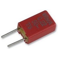
CAPACITOR PET FILM 0.1UF, 63V, RADIAL
Manufacturer
WIMA
Series
MKS 02r
Datasheet
1.MKS0C021000B00KSSD.pdf
(4 pages)
Specifications of MKS0C031000C00KSSD
Capacitor Dielectric Type
Polyethylene Naphthalate
Capacitance Tolerance
± 20%
Voltage Rating
63VDC
Capacitor Case Style
Radial Leaded
No. Of Pins
2
Capacitance
0.1µF
Tolerance
10 %
Termination Style
Radial
Dimensions
3 mm W x 4.6 mm L x 7.5 mm H
Lead Spacing
2.5 mm
Operating Temperature Range
- 55 C to + 100 C
Dissipation Factor Df
8
Product
Metallized Polyester Film Capacitors
Lead Free Status / RoHS Status
Lead free / RoHS Compliant
Available stocks
Company
Part Number
Manufacturer
Quantity
Price

Part Number:
MKS0C031000C00KSSD
Manufacturer:
WIMA
Quantity:
20 000


30
Continuation
General Data
Capacitance
* AC voltage: f = 50 Hz; 1.4 x U
** PCM = Printed circuit module = lead spacing
Dims. in mm.
Taped version see page 100.
d = 0.4 l
Rights reserved to amend design data without prior notification.
1000 pF
1500 „
2200 „
3300 „
4700 „
6800 „
0.01 mF
0.015 „
0.022 „
0.033 „
0.047 „
0.068 „
0.1
0.15 „
0.22 „
0.33 „
0.47 „
0.68 „
1.0
WIMA MKS 02
New range.
mF
mF
2.5
2.5
2.5
2.5
2.5
2.5
2.5
2.5
2.5
2.5
2.5
2.5
2.5
3
3
3.8
4.6
4.6
5.5
W
6
-2
W
50 VDC/30 VAC*
d
10
at the lead exit points
5.5
5.5
5.5
5.5
5.5
5.5
5.5
5.5
5.5
5.5
5.5
5.5
5.5
7.5
7.5
8.5
9
9
H
H
(
G
L
PCM
2.5
4.6
4.6
4.6
4.6
4.6
4.6
4.6
4.6
4.6
4.6
4.6
4.6
4.6
4.6
4.6
4.6
4.6
4.6
4.6
0.5)
L
rms
PCM**
+ UDC
2.5
2.5
2.5
2.5
2.5
2.5
2.5
2.5
2.5
2.5
2.5
2.5
2.5
2.5
2.5
2.5
2.5
2.5
2.5
2.5
2.5
2.5
2.5
2.5
2.5
2.5
2.5
2.5
2.5
2.5
3
3
3
3
3.8
4.6
5.5
W
U
r
63 VDC/40 VAC*
10
7
7
7
7
7
7
7
7
7
7
7
7.5
7.5
7.5
7.5
8.5
9
H
4.6
4.6
4.6
4.6
4.6
4.6
4.6
4.6
4.6
4.6
4.6
4.6
4.6
4.6
4.6
4.6
4.6
4.6
L
PCM**
2.5
2.5
2.5
2.5
2.5
2.5
2.5
2.5
2.5
2.5
2.5
2.5
2.5
2.5
2.5
2.5
2.5
2.5
2.5
2.5
2.5
2.5
2.5
2.5
2.5
2.5
2.5
2.5
2.5
3
3
3.8
4.6
5.5
W
100 VDC/63 VAC*
10
7
7
7
7
7
7
7
7
7
7
7
7.5
7.5
8.5
9
0.01
H
S
0.1
Z
10
1
7
5
3
7
5
3
0.1
Impedance change with frequency
(general guide).
4.6
4.6
4.6
4.6
4.6
4.6
4.6
4.6
4.6
4.6
4.6
4.6
4.6
4.6
4.6
4.6
L
3
PCM**
5 7
2.5
2.5
2.5
2.5
2.5
2.5
2.5
2.5
2.5
2.5
2.5
2.5
2.5
2.5
2.5
2.5
1
2.5
2.5
2.5
2.5
2.5
2.5
2.5
2.5
2.5
3
3.8
4.6
5.5
W
3
250 VDC/160 VAC*
5 7
10
10
7
7
7
7
7
7
7
7
7
7.5
8.5
9
H
f/MHz
4.6
4.6
4.6
4.6
4.6
4.6
4.6
4.6
4.6
4.6
4.6
4.6
4.6
L
100
PCM**
2.5
2.5
2.5
2.5
2.5
2.5
2.5
2.5
2.5
2.5
2.5
2.5
2.5
D
Related parts for MKS0C031000C00KSSD
Image
Part Number
Description
Manufacturer
Datasheet
Request
R

Part Number:
Description:
Specifications: Manufacturer: WIMA ; Product Category: DC Link Film Capacitors ; RoHS: Details ; Capacitance: 25 uF ; Tolerance: 5 % ; Voltage Rating: 450 Volts ; Series: DC-Link MKP 4 ; Termination Style: Radial ; Dimensions: 20 mm W x 41.5 mm
Manufacturer:
WIMA
Datasheet:

Part Number:
Description:
Polyester Film Capacitors 63V .01uF 10%
Manufacturer:
WIMA

Part Number:
Description:
Polyester Film Capacitors 250V .47uF 10%
Manufacturer:
WIMA
Datasheet:
Part Number:
Description:
Polyester Film Capacitors 630V .1uF 10%
Manufacturer:
WIMA
Datasheet:
Part Number:
Description:
Polyester Film Capacitors 63V 2.2uF 10% PCM 10
Manufacturer:
WIMA
Datasheet:
Part Number:
Description:
Polyester Film Capacitors 630V .015uF 10% PCM 7.5
Manufacturer:
WIMA
Datasheet:

Part Number:
Description:
Polyester Film Capacitors 100V 1000pF 10%
Manufacturer:
WIMA
Part Number:
Description:
Polyester Film Capacitors 100V .01uF 10%
Manufacturer:
WIMA
Datasheet:
Part Number:
Description:
Polyester Film Capacitors 630V .068uF 10%
Manufacturer:
WIMA
Datasheet:

Part Number:
Description:
Metallized Polyphenylene-sulphide Pps Capacitors In Pcm 5 Mm
Manufacturer:
WIMA
Datasheet:
Part Number:
Description:
Polypropylene Pp Film And Foil Capacitors For Pulse Applications In Pcm 2.5 Mm
Manufacturer:
WIMA
Datasheet:
Part Number:
Description:
Polypropylene Pp Film And Foil Capacitors For Pulse Applications In Pcm 5 Mm
Manufacturer:
WIMA
Datasheet:
Part Number:
Description:
Polypropylene Pp Capacitors For Pulse Applications With Metal Foil Electrodes, Schoopage Contacts And Self-healing, Internal Series Connection For Increased Current Carrying Capability Pcm 15 Mm To 37.5 Mm
Manufacturer:
WIMA
Datasheet:
Part Number:
Description:
Polypropylene Pp Film And Foil Capacitors For Pulse Applications Pcm 7.5 Mm To 15 Mm
Manufacturer:
WIMA
Datasheet: