MKT1813410635G Vishay, MKT1813410635G Datasheet - Page 8
MKT1813410635G
Manufacturer Part Number
MKT1813410635G
Description
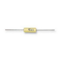
CAPACITOR, 0.1UF 630V CAPACITOR, 0.1UF 630V
Manufacturer
Vishay
Series
MKT1813r
Datasheet
1.MKT1813-310404.pdf
(13 pages)
Specifications of MKT1813410635G
Capacitance
0.1UF
Voltage Rating, Ac
220V
Voltage Rating, Dc
630V
Capacitor Dielectric Type
POLYESTER
Tolerance,
10%
Tolerance, -
10%
Temp, Op. Max
100(DEGREE C)
Rohs Compliant
YES


MKT 1813
Vishay Roederstein
POWER DISSIPATION AND MAXIMUM COMPONENT TEMPERATURE RISE
The power dissipation must be limited in order not to exceed the maximum allowed component temperature rise as a function of
the free ambient temperature.
The power dissipation can be calculated according type detail specification “HQN-384-01/101: Technical Information Film
Capacitors”.
The component temperature rise (ΔT) can be measured (see section “Measuring the component temperature” for more details)
or calculated by ΔT = P/G:
MEASURING THE COMPONENT TEMPERATURE
A thermocouple must be attached to the capacitor body as in:
The temperature is measured in unloaded (T
The temperature rise is given by ΔT = T
To avoid radiation or convection, the capacitor should be tested in a wind-free box.
APPLICATION NOTE AND LIMITING CONDITIONS
These capacitors are not suitable for mains applications as across-the-line capacitors without additional protection, as described
hereunder. These mains applications are strictly regulated in safety standards and therefore electromagnetic interference
suppression capacitors conforming the standards must be used.
To select the capacitor for a certain application, the following conditions must be checked:
1. The peak voltage (U
2. The peak-to-peak voltage (U
3. The voltage peak slope (dU/dt) shall not exceed the rated voltage pulse slope in an RC-circuit at rated voltage and without
4. The maximum component surface temperature rise must be lower than the limits (see figure max. allowed component
www.vishay.com
24
ringing. If the pulse voltage is lower than the rated DC voltage, the rated voltage pulse slope may be multiplied by U
divided by the applied voltage.
For all other pulses following equation must be fulfilled:
T is the pulse duration
The rated voltage pulse slope is valid for ambient temperatures up to 85 °C. For higher temperatures a derating factor of 3 %
per K shall be applied.
temperature rise).
2
• ΔT = Component temperature rise (°C)
• P = Power dissipation of the component (mW)
• G = Heat conductivity of the component (mW/°C)
×
T
∫
0
⎛
⎝
dU
------- -
dt
⎞
⎠
2
×
dt U
<
Rdc
P
) shall not be greater than the rated DC voltage (U
×
⎛
⎝
dU
------- -
dt
⎞
⎠
P-P
rated
) shall not be greater than 2
For technical questions, contact: dc-film@vishay.com
C
- T
amb
amb
.
) and maximum loaded condition (T
DC Film Capacitor
MKT Axial Type
√
2 x U
Rac
to avoid the ionisation inception level
Thermocouple
Rdc
)
C
).
Document Number: 26013
Revision: 08-Dec-08
Rdc
and
Related parts for MKT1813410635G
Image
Part Number
Description
Manufacturer
Datasheet
Request
R

Part Number:
Description:
357-036-542-201 CARDEDGE 36POS DL .156 BLK LOPRO
Manufacturer:
Vishay
Datasheet:
Part Number:
Description:
357-036-542-201 CARDEDGE 36POS DL .156 BLK LOPRO
Manufacturer:
Vishay
Datasheet:
Part Number:
Description:
357-036-542-201 CARDEDGE 36POS DL .156 BLK LOPRO
Manufacturer:
Vishay
Datasheet:
Part Number:
Description:
357-036-542-201 CARDEDGE 36POS DL .156 BLK LOPRO
Manufacturer:
Vishay
Datasheet:
Part Number:
Description:
357-036-542-201 CARDEDGE 36POS DL .156 BLK LOPRO
Manufacturer:
Vishay
Datasheet:
Part Number:
Description:
357-036-542-201 CARDEDGE 36POS DL .156 BLK LOPRO
Manufacturer:
Vishay
Datasheet:
Part Number:
Description:
357-036-542-201 CARDEDGE 36POS DL .156 BLK LOPRO
Manufacturer:
Vishay
Datasheet:
Part Number:
Description:
357-036-542-201 CARDEDGE 36POS DL .156 BLK LOPRO
Manufacturer:
Vishay
Datasheet:
Part Number:
Description:
357-036-542-201 CARDEDGE 36POS DL .156 BLK LOPRO
Manufacturer:
Vishay
Datasheet:
Part Number:
Description:
357-036-542-201 CARDEDGE 36POS DL .156 BLK LOPRO
Manufacturer:
Vishay
Datasheet:
Part Number:
Description:
357-036-542-201 CARDEDGE 36POS DL .156 BLK LOPRO
Manufacturer:
Vishay
Datasheet:
Part Number:
Description:
357-036-542-201 CARDEDGE 36POS DL .156 BLK LOPRO
Manufacturer:
Vishay
Datasheet:
Part Number:
Description:
357-036-542-201 CARDEDGE 36POS DL .156 BLK LOPRO
Manufacturer:
Vishay
Datasheet:
Part Number:
Description:
357-036-542-201 CARDEDGE 36POS DL .156 BLK LOPRO
Manufacturer:
Vishay
Datasheet:
Part Number:
Description:
357-036-542-201 CARDEDGE 36POS DL .156 BLK LOPRO
Manufacturer:
Vishay
Datasheet: