TPSR105K025R4000 AVX Corporation, TPSR105K025R4000 Datasheet
TPSR105K025R4000
Specifications of TPSR105K025R4000
Available stocks


Related parts for TPSR105K025R4000

TPSR105K025R4000 Summary of contents
Page 1
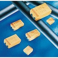
... C Surge Voltage (V ) +85°C: S Surge Voltage (V ) +125°C: S Temperature Range: Environmental Classification: Reliability: Termination Finished: 30 solid 2 electrolyte capacitors millimeters (inches) EIA EIA L±0.20 W+0.20 (0.008) Code Metric (0.008) -0.10 (0.004) A 1206 3216-18 3.20 (0.126) 1.60 (0.063) B 1210 3528-21 3.50 (0.138) 2 ...
Page 2
TPS Series Low ESR CAPACITANCE AND RATED VOLTAGE, VR (VOLTAGE CODE) RANGE (LETTER DENOTES CASE SIZE) Capacitance μF Code 2.5V (e) 4V (G) 6.3V (J) 0.15 154 0.22 224 0.33 334 0.47 474 0.68 684 1 105 1.5 155 2.2 ...
Page 3
... All technical data relates to an ambient temperature of +25°C. Capacitance and DF are measured at 120Hz, 0.5V RMS with a maximum DC bias of 2.2 volts. DCL is measured at rated voltage after 5 minutes. The EIA & CECC standards for low ESR Solid Tantalum Capacitors allow an ESR movement to 1.25 times catalogue limit post mounting. For typical weight and composition see page 124. ...
Page 4
... All technical data relates to an ambient temperature of +25°C. Capacitance and DF are measured at 120Hz, 0.5V RMS with a maximum DC bias of 2.2 volts. DCL is measured at rated voltage after 5 minutes. The EIA & CECC standards for low ESR Solid Tantalum Capacitors allow an ESR movement to 1.25 times catalogue limit post mounting. For typical weight and composition see page 124. ...
Page 5
... All technical data relates to an ambient temperature of +25°C. Capacitance and DF are measured at 120Hz, 0.5V RMS with a maximum DC bias of 2.2 volts. DCL is measured at rated voltage after 5 minutes. The EIA & CECC standards for low ESR Solid Tantalum Capacitors allow an ESR movement to 1.25 times catalogue limit post mounting. For typical weight and composition see page 124. ...
Page 6
... All technical data relates to an ambient temperature of +25°C. Capacitance and DF are measured at 120Hz, 0.5V RMS with a maximum DC bias of 2.2 volts. DCL is measured at rated voltage after 5 minutes. The EIA & CECC standards for low ESR Solid Tantalum Capacitors allow an ESR movement to 1.25 times catalogue limit post mounting. For typical weight and composition see page 124. ...
Page 7
... All technical data relates to an ambient temperature of +25°C. Capacitance and DF are measured at 120Hz, 0.5V RMS with a maximum DC bias of 2.2 volts. DCL is measured at rated voltage after 5 minutes. The EIA & CECC standards for low ESR Solid Tantalum Capacitors allow an ESR movement to 1.25 times catalogue limit post mounting. For typical weight and composition see page 124. ...
Page 8
... All technical data relates to an ambient temperature of +25°C. Capacitance and DF are measured at 120Hz, 0.5V RMS with a maximum DC bias of 2.2 volts. DCL is measured at rated voltage after 5 minutes. The EIA & CECC standards for low ESR Solid Tantalum Capacitors allow an ESR movement to 1.25 times catalogue limit post mounting. For typical weight and composition see page 124. ...
Page 9
... All technical data relates to an ambient temperature of +25°C. Capacitance and DF are measured at 120Hz, 0.5V RMS with a maximum DC bias of 2.2 volts. DCL is measured at rated voltage after 5 minutes. The EIA & CECC standards for low ESR Solid Tantalum Capacitors allow an ESR movement to 1.25 times catalogue limit post mounting. For typical weight and composition see page 124. ...
Page 10
... All technical data relates to an ambient temperature of +25°C. Capacitance and DF are measured at 120Hz, 0.5V RMS with a maximum DC bias of 2.2 volts. DCL is measured at rated voltage after 5 minutes. The EIA & CECC standards for low ESR Solid Tantalum Capacitors allow an ESR movement to 1.25 times catalogue limit post mounting. For typical weight and composition see page 124. ...
Page 11
... All technical data relates to an ambient temperature of +25°C. Capacitance and DF are measured at 120Hz, 0.5V RMS with a maximum DC bias of 2.2 volts. DCL is measured at rated voltage after 5 minutes. The EIA & CECC standards for low ESR Solid Tantalum Capacitors allow an ESR movement to 1.25 times catalogue limit post mounting. For typical weight and composition see page 124. ...