B82498F1681J000 EPCOS Inc, B82498F1681J000 Datasheet
B82498F1681J000
Specifications of B82498F1681J000


Related parts for B82498F1681J000


B82498F1681J000 Summary of contents
Page 1
SMT inductors SIMID series, SIMID 0805-F Series/Type: B82498F Date: March 2008 Data Sheet Data Sheet EPCOS AG 2008. Reproduction, publication and dissemination of this publication and the information contained therein without EPCOS’ prior express consent is prohibited. ...
Page 2
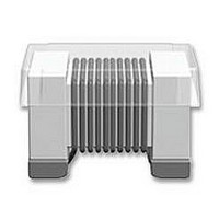
SMT inductors, SIMID series SIMID 0805-F Size 0805 (EIA) and/or 2012 (IEC) Rated inductance 2 6800 nH Rated current 1000 mA Construction ■ Cubic coil with ceramic or ferrite core ■ Epoxy-molded flat top for ...
Page 3
SMT inductors, SIMID series SIMID 0805-F Dimensional drawing and layout recommendation 2.3 max. 2+0.2 Metallization Welding area Epoxy coating 1) 1) 0.5±0.1 0.5±0.1 1) Soldering area 2) This area (30% of contact area) should not be used to assess solderability ...
Page 4
SMT inductors, SIMID series SIMID 0805-F Technical data and measuring conditions Rated inductance factor Q min Rated temperature T R Rated current I R Self-resonance frequency f res,min DC resistance R max Solderability (lead-free) Resistance to soldering ...
Page 5
SMT inductors, SIMID series SIMID 0805-F Characteristics and ordering codes L Tolerance MHz Core material: ceramic ±10% 2 250 5.6 250 6.8 250 8.2 250 ± 250 ±5% 12 250 ^ ...
Page 6
SMT inductors, SIMID series SIMID 0805-F Characteristics and ordering codes L Tolerance MHz Core material: ferrite ±5% 1000 ^ J 7.96 1200 7.96 1500 7.96 1800 7.96 2200 7.96 2700 7.96 3300 7.96 3900 7.96 4700 ...
Page 7
SMT inductors, SIMID series SIMID 0805-F Impedance |Z| vs. frequency f (ceramic core) measured with impedance analyzer Agilent 4291A, typical values at 20 ° B82498F Ω | 820 nH 3 470 nH 10 100 nH 2 ...
Page 8
SMT inductors, SIMID series SIMID 0805-F Inductance L versus DC load current I measured with RF LCR meter Agilent 4275A, typical values at 20 ° 6.8 µH µH 4.7 µH L 2.7 µH 1 µ 0.82 ...
Page 9
Cautions and warnings ■ Please note the recommendations in our Inductors data book (latest edition) and in the data sheets. – Particular attention should be paid to the derating curves given there. – The soldering conditions should also be observed. ...
Page 10
Important notes The following applies to all products named in this publication: 1. Some parts of this publication contain statements about the suitability of our products for certain areas of application. These statements are based on our knowledge of typical ...