3610S-1-102 Bourns Inc., 3610S-1-102 Datasheet
3610S-1-102
Manufacturer Part Number
3610S-1-102
Description
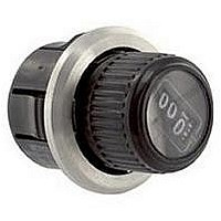
POT DIGITAL, 1KOHM 10TURN, 5%, 1.5W
Manufacturer
Bourns Inc.
Series
3610r
Type
Potentiometerr
Specifications of 3610S-1-102
Track Resistance
1kohm
Resistance Tolerance
± 5%
Power Rating
1.5W
Adjustment Type
Knob
Temperature Coefficient
± 50ppm
Resistance Min
1ohm
Resistance
1 KOhms
Tolerance
5 %
Termination Style
Lug
Number Of Turns
10
Shaft Type
Knob
Shaft Length
18.8 mm
Shaft Diameter
22.23 mm
Dimensions
22.23 mm Dia.
Product
Precision Potentiometers
Angle, Mechanical
3600 °
Diameter, Shaft
0.25 "
Dielectric Strength
1000 VAC
Linearity
±0.25 %
Mounting Type
Snap-In
Power, Rating
1.5 W
Resistance, Insulation
1000 Megohms
Resolution
0.035 %
Rotational Life
50000 Revolutions
Temperature, Operating, Maximum
+85 °C
Temperature, Operating, Minimum
+1 °C
Terminal Type
Solder Lug
Termination
Solderable Pins
Thread Length
0.375 in.
Torque
1 to 7 Oz./in.
Operating Temperature Range
+1°C To +85°C
Rohs Compliant
No
No. Of Gangs
1
Leaded Process Compatible
No
No. Of Turns
10
Lead Free Status / RoHS Status
Contains lead / RoHS non-compliant
Available stocks
Company
Part Number
Manufacturer
Quantity
Price
Company:

Part Number:
3610S-1-102
Manufacturer:
BOURNS
Quantity:
1 000
Standard Resistance Range ...................................................................................100 to 100 K ohms
Total Resistance Tolerance ...........................................................................................................±5 %
Effective Electrical Angle ...............................................................................................3600 ° nominal
Absolute Minimum Resistance.................................1 ohm or 0.1 % maximum (whichever is greater)
Noise.............................................................................................................100 ohms ENR maximum
Dielectric Withstanding Voltage (MIL-STD-202, Method 301)
Power Rating (Voltage Limited By Power Dissipation or 385 VAC, Whichever is Less)
Insulation Resistance (500 VDC)..................................................................1,000 megohms minimum
Resolution ........................................................................................See recommended part numbers
Accuracy (Correlation of Dial Readout to Voltage Ratio Output) .........................±0.5 % voltage ratio
Repeatability of Dial Readout ...............................................................................±0.1 % voltage ratio
Operating Temperature Range.....................................................................................+1 °C to +85 °C
Storage Temperature Range.......................................................................................-25 °C to +85 °C
Temperature Coefficient Over Storage Temperature Range
Vibration .........................................................................................................................................10 G
Shock .............................................................................................................................................50 G
Load Life ............................................................................................................1,000 hours, 1.5 watts
Rotational Life (No Load) ...............................................................................50,000 shaft revolutions
Moisture Resistance (MIL-STD-202, Method 103, Condition B)
IP Rating ........................................................................................................................................IP 60
Stop Strength.........................................................................................14 N-cm (20 oz.-in.) minimum
Mechanical Angle ......................................................................................................3600 ° +20 °, -0 °
Torque (Starting) .........................................................0.71 to 4.94 N-cm (1.0 to 7.0 oz.-in.) maximum
Torque (Running) ...............................................................................4.94 N-cm (7.0 oz.-in.) maximum
Backlash ........................................................................................................................1.0 ° maximum
Weight..................................................................................................................Approximately 20 gm
Terminals ..............................................................................................................Gold-plated J-Hooks
Markings...............................Manufacturer’s name and part number, resistance value and tolerance,
1
At room ambient: +25 °C nominal and humidity nominal, except as noted.
Recommended Part Numbers
Electrical Characteristics
Environmental Characteristics
Mechanical Characteristics
Part Number
3610S-1-102
3610S-1-502
3610S-1-103
Sea Level ..........................................................................................................1,000 VAC minimum
70,000 Feet..........................................................................................................400 VAC minimum
+25 °C .................................................................................................................................1.5 watts
+85 °C......................................................................................................................................0 watt
Wiper Bounce ...........................................................................................0.1 millisecond maximum
Total Resistance Shift ..............................................................................................±2 % maximum
Voltage Ratio Shift ................................................................................................±0.2 % maximum
Total Resistance Shift ..............................................................................................±2 % maximum
Total Resistance Shift ..............................................................................................±2 % maximum
Total Resistance Shift ..............................................................................................±2 % maximum
Variation ........................................................................................0.71 N-cm (1.0 oz.-in.) maximum
Soldering Condition ....................Recommended hand soldering using Sn95/Ag5 no clean solder,
Resistance
10,000
1,000
5,000
(Ω)
0.025 ” wire diameter. Maximum temperature 399 °C (750 °F) for 3 seconds.
1
Resolution
1
.035
.027
.022
(%)
1
No wash process to be used with no clean flux.
3610 - 10-Turn Precision Knobpot
Features
BOLDFACE LISTINGS ARE IN STOCK AND READILY
AVAILABLE THROUGH DISTRIBUTION.
FOR OTHER OPTIONS CONSULT FACTORY.
Snap-in mounting
Space saving - extends only 5/8 ” behind
most panels
Easy one-hole, snap-in mounting
Digital dial provides excellent readability
2
......................±50 ppm/°C maximum/wire
wiring diagram, and date code.
Customers should verify actual device performance in their specific applications.
22.23
(7/8)
DIA.
VIEW ROTATED 45 °
ANTIROTATION
“Knobpot” is a registered trademark of Bourns, Inc.
Specifications are subject to change without notice.
CCW
KEY
(.740 ± .015)
14.27
(.562)
18.80 ± .38
1
NOTES:
1. SNAP-IN MOUNTING CUP
TOLERANCES: EXCEPT WHERE NOTED
DECIMALS: .XX ±
FRACTIONS: ±1/64
DIMENSIONS:
(.025)
THRU NO. 14GA) AND (.125)
®
ACCOMMODATES PANEL THICKNESS
.64
PANEL HOLE PATTERN
CLOCKWISE
THRU
(IN.)
(.078)
MM
2
1.98
1 3
2
(.010),
.25
WIPER
(NO. 22GA
FULL R
(.1285)
3.264
.XXX ±
3.18
(1.00)
(.640 ± .015)
25.40
(NO. 30 DRILL)
16.26 ± .38
(.498)
12.65
(.005)
.13
3
(.0285)
ANTIROTATION
KEY
#21 AWG GOLD
PLATED PINS
LOCATED ON
(.050)
REV. 11/04
1.27
DIA.
.724
(3/16 ± 1/32)
CW
(1.240)
31.496
REF.
4.76 ± .79
DIA.
RADIUS
DIA.
Related parts for 3610S-1-102
Image
Part Number
Description
Manufacturer
Datasheet
Request
R

Part Number:
Description:
POT DIGITAL, 5KOHM 10TURN, 5%, 1.5W
Manufacturer:
Bourns Inc.
Datasheet:
Part Number:
Description:
POT 50K OHM 7/8" RD WW
Manufacturer:
Bourns Inc.
Datasheet:
Part Number:
Description:
POT DIGITAL, 100KOHM 10TURN 5% 1.5W
Manufacturer:
Bourns Inc.
Datasheet:
Part Number:
Description:
POT DIGITAL, 2KOHM 10TURN, 5%, 1.5W
Manufacturer:
Bourns Inc.
Datasheet:
Part Number:
Description:
POT DIGITAL, 20KOHM 10TURN 5%, 1.5W
Manufacturer:
Bourns Inc.
Datasheet:

Part Number:
Description:
POT DIGITAL, 200OHM 10TURN 5%, 1.5W
Manufacturer:
Bourns Inc.
Datasheet:
Part Number:
Description:
Precision Potentiometers 500ohm 10Turn SnapIn
Manufacturer:
Bourns Inc.
Datasheet:
Part Number:
Description:
PRECISION POT - 7/8" 22MM DIA 10T WW
Manufacturer:
Bourns Inc.
Datasheet:
Part Number:
Description:
PRECISION POT - 7/8" 22MM DIA 10T WW
Manufacturer:
Bourns Inc.
Datasheet:

Part Number:
Description:
Manufacturer:
Bourns, Inc.
Datasheet:
Part Number:
Description:
11mm Potentiometer
Manufacturer:
Bourns, Inc.
Datasheet: