3501H-1-104L Bourns Inc., 3501H-1-104L Datasheet
3501H-1-104L
Manufacturer Part Number
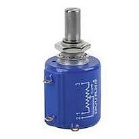
3501H-1-104L
Description
POT, WIREWOUND, 100KOHM, 10%, 2W
Manufacturer
Bourns Inc.
Series
3501r
Datasheet
1.3501H-1-102L.pdf
(1 pages)
Specifications of 3501H-1-104L
Track Resistance
100kohm
Track Taper
Linear
No. Of Turns
10
Resistance Tolerance
± 10%
Power Rating
2W
Potentiometer Mounting
Panel
No. Of Gangs
2
Adjustment Type
Side
Lead Free Status / RoHS Status
Lead free / RoHS Compliant
Electrical Characteristics
Standard Resistance Range ..........50 to 100K ohms....................1K to 100K ohms
Resistance Tolerance......................±3% ......................................±10%
Independent Linearity ....................±0.20% ..................................±0.25%
Resolution ......................................See ordering information........Essentially infinite
Effective Electrical Angle ................3600° +10°, -0° ......................3600° +10°, -2°
Absolute Minimum Resistance/......1 ohm or 0.1% maximum ......Minimum voltage 0.2%
Noise ..............................................100 ohms ENR maximum ......Output smoothness 0.1%
Power Rating (Voltage Limited
Dielectric Withstanding Voltage......MIL-STD-202, Method 301 ....MIL-STD-202, Method 301
Insulation Resistance
E
Operating Temperature
Temperature Coefficient
Vibration..........................................20G ........................................20G
Shock..............................................100G ......................................100G
Load Life ........................................1,000 hours, 2 watts ..............1,000 hours, 2 watts
Rotational Life (No Load) ................2,000,000 shaft revolutions
Moisture Resistance ......................MIL-STD-202, Method 103, ..MIL-STD-202, Method 103,
Mechanical Characteristics
Mechanical Angle ..........................3600° +10°, -0° ......................3600° +10°, -0°
Shaft Runout ..................................0.002 in. (0.05mm) T.I.R. ........0.002 in. (0.05mm) T.I.R.
Lateral Runout ................................0.005 in. (0.13mm) T.I.R. ........0.005 in. (0.13mm) T.I.R.
Pilot Diameter Runout ....................0.002 in. (0.05mm) T.I.R. ........0.002 in. (0.05mm) T.I.R.
Shaft End Play ................................0.005 in. (0.13mm) T.I.R. ........0.005 in. (0.13mm) T.I.R.
Shaft Radial Play ............................0.003 in. (0.08mm) T.I.R. ........0.003 in. (0.08mm) T.I.R.
Stop Strength ................................96 oz.-in. (67.8 Ncm) min.......96 oz.-in. (67.8 Ncm) min.
Torque (Starting & Running)............0.6 oz.-in. (0.42 Ncm) max.....0.6 oz-in. (0.42 Ncm) max.
Backlash ........................................1.0° maximum ........................1.0° maximum
Weight ............................................Approximately 28G ................Approximately 28G
Terminals ........................................Gold-plated solder lugs ........Gold-plated turret lugs
Ganging ..........................................2 cups maximum....................2 cups maximum
270
1
2
At room ambient: +25°C nominal and 50% relative humidity nominal, except as noted.
Consult manufacturer for complete specification details for resistances below 500 ohms.
Bourns
Model 3500/3501
nvironmental Characteristics
Minimum Voltage ........................(whichever is greater) ............maximum
By Power Dissipation or
325 VAC, Whichever Is Less)
+70°C ..........................................2 watts ..................................2 watts
+125°C ........................................0 watt ....................................0 watt
Sea Level ....................................1,500 VAC minimum ..............1,500 VAC minimum
70,000 Feet ..................................400 VAC minimum ................400 VAC minimum
(500 VDC) ....................................1,000 megohms minimum ....1,000 megohms minimum
Static Operation Temp Range......-65°C to +125°C ....................-65°C to +125°C
Dynamic Temp Range..................+1°C to +125°C......................+1°C to +125°C
Wiper Bounce ..............................0.1 millisecond maximum ......0.1 millisecond maximum
Total Resistance Shift ..................±2% maximum ......................±2% maximum
Voltage Ratio Shift ......................±0.1% maximum....................±0.1% maximum
Wiper Bounce ..............................0.1 millisecond maximum ......0.1 millisecond maximum
Total Resistance Shift ..................±2% maximum ......................±2% maximum
Voltage Ratio Shift ......................±0.1% maximum....................±0.1% maximum
Total Resistance Shift ..................±2% maximum ......................±5% maximum
Total Resistance Shift ..................±5% maximum ......................±5% maximum
Total Resistance Shift ..................±2% maximum ......................±5% maximum
....................................................................................................maximum
®
Precision Potentiometers
2
..............±50ppm/°C maximum/unit ....±100ppm/°C maximum/unit
1
1
1
Wirewound Element
Condition B
3500
7/8” (22MM) DIAMETER / 10-TURN /
WIREWOUND AND HYBRITRON
FOR ORDERING INFORMATION SEE PAGE 296.
Bushing mount
Sealable
Non-standard features and
specifications available
2
..4,000,000 shaft revolutions
Hybritron
Condition B
3501
®
Element
WIPER
3500S-2/3501H-1
Optional high torque feature
Optional center tap feature
Gangable
(16.0) R
MAX.
Specifications are subject to change without notice.
CCW
.63
(5.46 ± .76)
.215 ± .030
(25.4 ± .51)
CCW
.315 ± .015
(8.0 ± .38)
1.00 ± .02
NOTE: LOCKWASHER AND HEX NUT TO BE
NOTE: SHAFT LENGTH VARIATIONS
3500S-2-RC
3501H-1-RC
13/16 ± 1/32
(20.64 ±.79)
45° ± 5°
TOLERANCES: EXCEPT WHERE NOTED
DECIMALS: .XX ±
FRACTIONS: ±1/64
DIMENSIONS:
1
CW
SUPPLIED WITH EACH UNIT.
3500S-1-RC
(22.23)
CLOCKWISE
7/8
®
(MM)
IN.
ELEMENT
(1.52)
45° ± 5°
.06
.010
(.25),
(8.9)
(17.46)
(20.64)
2
(20.64)
.35
13/16
13/16
11/16
LOCATION OF OPTIONAL
A/R PIN ON 7.37 R
.032 ± .010
.XXX ±
WIPER
(.81 ± .25)
(.81)
.032
ADJUSTMENT SLOT
3/8"-32 2A THD UNEF
.010
(.25)
.249+.0000/-.0003
WIDE X
.005
(.13)
(6.34 + .00/- .01)
(12.7)
(10.32 + .00/ - .05)
1/2
.4062+.000/-.002
X 45° CHAMFER
DEEP
3
PILOT DIA.
REF.
CW
DIA.
Related parts for 3501H-1-104L
Image
Part Number
Description
Manufacturer
Datasheet
Request
R

Part Number:
Description:
PRECISION POT-10T HYBRID-BUSH
Manufacturer:
Bourns Inc.
Datasheet:

Part Number:
Description:
POT 1.0K OHM 7/8" RD HYBRITRON
Manufacturer:
Bourns Inc.
Datasheet:
Part Number:
Description:
POT 10K OHM 7/8" RD HYBRITRON
Manufacturer:
Bourns Inc.
Datasheet:
Part Number:
Description:
POT 5.0K OHM 7/8" RD HYBRITRON
Manufacturer:
Bourns Inc.
Datasheet:
Part Number:
Description:
Precision Potentiometers 7/8 HYBR 50KOHMS 0.25% 10TURNS
Manufacturer:
Bourns Inc.
Datasheet:

Part Number:
Description:
Manufacturer:
Bourns, Inc.
Datasheet:
Part Number:
Description:
11mm Potentiometer
Manufacturer:
Bourns, Inc.
Datasheet:
Part Number:
Description:
Manufacturer:
Bourns, Inc.
Datasheet:
Part Number:
Description:
Manufacturer:
Bourns, Inc.
Datasheet:
Part Number:
Description:
Manufacturer:
Bourns, Inc.
Datasheet:
Part Number:
Description:
5/16 Round Trimming Potentiometer
Manufacturer:
Bourns, Inc.
Datasheet: