CCF55100RFKE36 Vishay, CCF55100RFKE36 Datasheet - Page 2
CCF55100RFKE36
Manufacturer Part Number
CCF55100RFKE36
Description
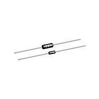
RESISTOR, METAL FILM, 100OHM, 500mW, 1%
Manufacturer
Vishay
Series
CCF55r
Type
Metal Filmr
Datasheet
1.CCF55191RFKE36.pdf
(3 pages)
Specifications of CCF55100RFKE36
Resistance
100ohm
Resistance Tolerance
± 1%
Power Rating
500mW
Voltage Rating
250V
Resistor Element Material
Metal Film
Temperature Coefficient
± 100ppm/°C
Tolerance
1 %
Termination Style
Axial
Operating Temperature Range
- 65 C to + 165 C
Dimensions
2.29 mm Dia. x 6.73 mm L
Product
Metal Film Resistors High Reliability
Power Rating(s)
1/4 or 1/2W
Tolerance (+ Or -)
1%
Operating Temp Range
-65C to 165C
Case Style
Conformal
Failure Rate
Not Required
Lead Spacing (nom)
Not Requiredmm
Product Length (mm)
6.73mm
Product Depth (mm)
Not Requiredmm
Product Height (mm)
Not Requiredmm
Construction
Cylindrical
Lead Free Status / RoHS Status
Lead free / RoHS Compliant
Lead Free Status / RoHS Status
Lead free / RoHS Compliant, Lead free / RoHS Compliant


DIMENSIONS in inches (millimeters)
Note
(1)
Document Number: 31015
Revision: 24-Sep-10
PRODUCT
CCF55
RESISTANCE VALUES
Vishay CCF55 is available in the standard 96 resistance values
per decade. Values are obtained from the following decade
table by multiplying by powers of 10. As an example: 30.1 can
represent 30.1 Ω, 301 Ω, 3.01 kΩ, 30.1 kΩ or 301 kΩ.
PERFORMANCE
RATED DISSIPATION, P
CCF55
TEST
Thermal Shock
Short Time Overload
Low Temperature Operation
Moisture Resistance
Resistance to Soldering Heat
Shock/Bump
Vibration
Life
Terminal Strength
Dielectric Withstanding Voltage
Test specifications as per IEC 60115-1
10.0
10.2
10.5
10.7
11.0
11.3
11.5
11.8
12.1
12.4
12.7
13.0
13.3
13.7
14.0
14.3
(1)
14.7
15.0
15.4
15.8
16.2
16.5
16.9
17.4
17.8
18.2
18.7
19.1
19.6
20.0
20.5
21.0
21.5
22.1
22.6
23.2
23.7
24.3
24.9
25.5
26.1
26.7
27.4
28.0
28.7
29.4
30.1
30.9
70
0.245 ± 0.020
(6.22 ± 0.51)
A
31.6
32.4
33.2
34.0
34.8
35.7
36.5
37.4
38.3
39.2
40.2
41.2
42.2
43.2
44.2
45.3
Metal Film Resistors, Industrial, ± 1 % Tolerance
For technical questions, contact:
46.4
47.5
48.7
49.9
51.1
52.3
53.6
54.9
56.2
57.6
59.0
60.4
61.9
63.4
64.9
66.5
0.090 ± 0.008
(2.29 ± 0.20)
B
68.1
69.8
71.5
73.2
75.0
76.8
78.7
80.6
82.5
84.5
86.6
88.7
90.9
93.1
95.3
97.6
MAXIMUM ΔR
± 0.5 %
± 0.5 %
± 0.5 %
± 1.5 %
± 0.5 %
± 0.5 %
± 0.5 %
± 0.5 %
± 0.2 %
± 0.5 %
1/4 W
(Max.)
A
C
filmresistorsleaded@vishay.com
DERATING
MARKING
The nominal resistance and tolerance are marked on the
resistor using five colored bands in accordance with IEC 60062,
marking codes for resistors and capacitors.
120
100
(6.73)
(Max.)
0.265
B
80
60
40
20
- 65 - 50
0
C
E
D
- 25
0
0.023 ± 0.002
(0.60 ± 0.05)
25
D
50
70 75 100
MAXIMUM ΔR
AMBIENT TEMPERATURE IN °C
± 1.0 %
1/2 W
-
-
-
-
-
-
-
-
-
125 150 165 175 200
1.100 ± 0.040
(27.94 ± 1.02)
www.vishay.com
CCF55
E
Vishay
17
Related parts for CCF55100RFKE36
Image
Part Number
Description
Manufacturer
Datasheet
Request
R

Part Number:
Description:
357-036-542-201 CARDEDGE 36POS DL .156 BLK LOPRO
Manufacturer:
Vishay
Datasheet:
Part Number:
Description:
357-036-542-201 CARDEDGE 36POS DL .156 BLK LOPRO
Manufacturer:
Vishay
Datasheet:
Part Number:
Description:
357-036-542-201 CARDEDGE 36POS DL .156 BLK LOPRO
Manufacturer:
Vishay
Datasheet:
Part Number:
Description:
357-036-542-201 CARDEDGE 36POS DL .156 BLK LOPRO
Manufacturer:
Vishay
Datasheet:
Part Number:
Description:
357-036-542-201 CARDEDGE 36POS DL .156 BLK LOPRO
Manufacturer:
Vishay
Datasheet:
Part Number:
Description:
357-036-542-201 CARDEDGE 36POS DL .156 BLK LOPRO
Manufacturer:
Vishay
Datasheet:
Part Number:
Description:
357-036-542-201 CARDEDGE 36POS DL .156 BLK LOPRO
Manufacturer:
Vishay
Datasheet:
Part Number:
Description:
357-036-542-201 CARDEDGE 36POS DL .156 BLK LOPRO
Manufacturer:
Vishay
Datasheet:
Part Number:
Description:
357-036-542-201 CARDEDGE 36POS DL .156 BLK LOPRO
Manufacturer:
Vishay
Datasheet:
Part Number:
Description:
357-036-542-201 CARDEDGE 36POS DL .156 BLK LOPRO
Manufacturer:
Vishay
Datasheet:
Part Number:
Description:
357-036-542-201 CARDEDGE 36POS DL .156 BLK LOPRO
Manufacturer:
Vishay
Datasheet:
Part Number:
Description:
357-036-542-201 CARDEDGE 36POS DL .156 BLK LOPRO
Manufacturer:
Vishay
Datasheet:
Part Number:
Description:
357-036-542-201 CARDEDGE 36POS DL .156 BLK LOPRO
Manufacturer:
Vishay
Datasheet:
Part Number:
Description:
357-036-542-201 CARDEDGE 36POS DL .156 BLK LOPRO
Manufacturer:
Vishay
Datasheet:
Part Number:
Description:
357-036-542-201 CARDEDGE 36POS DL .156 BLK LOPRO
Manufacturer:
Vishay
Datasheet: