D2TO020C22R00FTE3 Vishay, D2TO020C22R00FTE3 Datasheet - Page 3
D2TO020C22R00FTE3
Manufacturer Part Number
D2TO020C22R00FTE3
Description
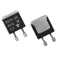
RESISTOR, THICK FILM, 22OHM, 20W, 1%
Manufacturer
Vishay
Series
D2TO20r
Datasheet
1.D2TO020C10000FTE3.pdf
(5 pages)
Specifications of D2TO020C22R00FTE3
Resistance
22ohm
Resistance Tolerance
± 1%
Power Rating
20W
Resistor Element Material
Thick Film
Resistor Case Style
TO-263 (D2PAK)
Temperature Coefficient
± 150ppm/°C
Tolerance
1 %
Termination Style
SMD/SMT
Package / Case
TO-263
Voltage Rating
250 Volts
Operating Temperature Range
- 55 C to + 150 C
Dimensions
8.8 mm W x 10.1 mm L x 4.5 mm H
Product
Thick Film Resistors SMD
Lead Free Status / RoHS Status
Lead free / RoHS Compliant
Available stocks
Company
Part Number
Manufacturer
Quantity
Price

Part Number:
D2TO020C22R00FTE3
Manufacturer:
VISHAY/威世
Quantity:
20 000


www.vishay.com
20
D2TO20
Vishay Sfernice
CHOICE OF THE BOARD
The user must choose the board according to the working conditions of the component (power, room temperature). Maximum
working temperature must not exeed 155 °C. The dissipated power is simply calculated by the following ratio:
P:
ΔT:
R
R
Example:
R
Thermal resistance R
Considering equation (1) we have:
ACCIDENTAL OVERLOAD
In any case the applied voltage must be lower than the maximum overload voltage of 375 V. The values indicated on the graph
below are applicable to resistors in air or mounted onto a board.
ENERGY CURVE
Single Pulse:
These informations are for a single pulse on a cold resistor at 25 °C (not already used for a dissipation) and for pulses of 100 ms
maximum duration.
The formula used to calculate E is:
with:
The energy calculated must be less than that allowed by the graph.
TH (j - c)
TH (c - a )
TH (c - a)
E (J):
P (W): Pulse power
t (s):
U (V): Pulse voltage
R (Ω): Resistor
:
:
for D2TO20 power rating 2.5 W at ambient temperature + 25 °C.
Pulse energy
Pulse duration
Expressed in W
Difference between maximum working temperature and room temperature
Thermal resistance value measured between resistive layer and outer side of the resistor. It is the thermal
resistance of the component: 6.5 °C/W.
Thermal resistance value measured between outer side of the resistor and room temperature. It is the thermal
resistance of the solder layer (according the quality of the soldering) and the thermal resistance of the board.
ΔT = 155 °C - 25 °C = 130 °C
R
R
TH (j - c)
TH (c - a)
TH (j - c)
+ R
= 52 °C/W - 6.5 °C/W = 45.5 °C/W
TH (c - a)
: 6.5 °C/W
= ΔT/P = 130/2.5 = 52 °C/W
0.01
100
0.1
10
1
10
-7
For technical questions, contact:
Surface Mounted Power Resistor
10
Thick Film Technology
-6
P
=
OVERLOAD DURATION IN s
-------------------------------------------------------------- -
[
R
TH (j - c)
E
10
-5
=
P x t
]
ΔT
+
[
10
R
=
TH (c - a)
-4
U
------ - x t
R
2
sfer@vishay.com
]
10
1 ( )
-3
10
-2
10
-1
Document Number: 51055
Revision: 30-Apr-10
Related parts for D2TO020C22R00FTE3
Image
Part Number
Description
Manufacturer
Datasheet
Request
R

Part Number:
Description:
357-036-542-201 CARDEDGE 36POS DL .156 BLK LOPRO
Manufacturer:
Vishay
Datasheet:
Part Number:
Description:
357-036-542-201 CARDEDGE 36POS DL .156 BLK LOPRO
Manufacturer:
Vishay
Datasheet:
Part Number:
Description:
357-036-542-201 CARDEDGE 36POS DL .156 BLK LOPRO
Manufacturer:
Vishay
Datasheet:
Part Number:
Description:
357-036-542-201 CARDEDGE 36POS DL .156 BLK LOPRO
Manufacturer:
Vishay
Datasheet:
Part Number:
Description:
357-036-542-201 CARDEDGE 36POS DL .156 BLK LOPRO
Manufacturer:
Vishay
Datasheet:
Part Number:
Description:
357-036-542-201 CARDEDGE 36POS DL .156 BLK LOPRO
Manufacturer:
Vishay
Datasheet:
Part Number:
Description:
357-036-542-201 CARDEDGE 36POS DL .156 BLK LOPRO
Manufacturer:
Vishay
Datasheet:
Part Number:
Description:
357-036-542-201 CARDEDGE 36POS DL .156 BLK LOPRO
Manufacturer:
Vishay
Datasheet:
Part Number:
Description:
357-036-542-201 CARDEDGE 36POS DL .156 BLK LOPRO
Manufacturer:
Vishay
Datasheet:
Part Number:
Description:
357-036-542-201 CARDEDGE 36POS DL .156 BLK LOPRO
Manufacturer:
Vishay
Datasheet:
Part Number:
Description:
357-036-542-201 CARDEDGE 36POS DL .156 BLK LOPRO
Manufacturer:
Vishay
Datasheet:
Part Number:
Description:
357-036-542-201 CARDEDGE 36POS DL .156 BLK LOPRO
Manufacturer:
Vishay
Datasheet:
Part Number:
Description:
357-036-542-201 CARDEDGE 36POS DL .156 BLK LOPRO
Manufacturer:
Vishay
Datasheet:
Part Number:
Description:
357-036-542-201 CARDEDGE 36POS DL .156 BLK LOPRO
Manufacturer:
Vishay
Datasheet:
Part Number:
Description:
357-036-542-201 CARDEDGE 36POS DL .156 BLK LOPRO
Manufacturer:
Vishay
Datasheet: