MCMF0W2FF1503A10 MULTICOMP, MCMF0W2FF1503A10 Datasheet - Page 2
MCMF0W2FF1503A10
Manufacturer Part Number
MCMF0W2FF1503A10
Description
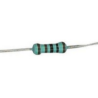
RESISTOR, METAL FILM, 150KOHM, 500mW, 1%
Manufacturer
MULTICOMP
Series
MFRr
Datasheet
1.MCMF0W2FF1000A10.pdf
(3 pages)
Specifications of MCMF0W2FF1503A10
Resistance
150kohm
Resistance Tolerance
± 1%
Power Rating
500mW
Voltage Rating
350V
Resistor Element Material
Metal Film
Temperature Coefficient
± 50ppm/°C
Lead Free Status / RoHS Status
Lead free / RoHS Compliant


DC. Resistance
Short time overload
Dielectric withstanding
voltage
Temperature coefficient
Resistance to soldering
heat
Characteristics
Pulse overload
Solderability
Load life in humidity
Resistance to solvent
Temperature cycling
Terminal strength
Load life
*RCWV = Rated Continuous Working Voltage =
Must be within the specified tolerance
Resistance change rate is
No evidence of flashover mechanical
Resistance change rate is
specified below:
±(0.5% +0.05 ) Max. with No
evidence of mechanical damage.
damage, arcing or insulation
breakdown.
±(1% +0.05 ) Max. with no evidence
of mechanical damage.
No deterioration of protective coating
Within the temperature coefficient
and markings.
Resistance change rate is
±(1% +0.05 ) Max. with no evidence
of mechanical damage.
No evidence of mechanical damage.
Resistance change rate is
±(1% +0.05 ) Max. with no evidence
of mechanical damage.
95% coverage Min.
Resistance Value
Resistance Value
Normal type
Normal type
±50 PPM/°C Maximum
Limits
±1.5%
±1.5%
R/R
R/R
below :
7.9 Resistance change after 1,000 hours (1.5 hours "ON, 0.5 hour
"OFF" ) at * RCWV in humidity test chamber controlled at
40°C±2°C and 90 to 95% relative humidity.
7.4 Resistance change after continuous five cycles for duty shown
R
R
5.7 Resistors shall be clamped in the trough of a 90° metallic
specified in sheet '1'
5.8 Resistance change after 10,000 cycles (1 second "ON",
25 seconds "OFF") at 4 times RCWV
7.10 Permanent resistance change after 1,000 hours operating at
* RCWV with duty cycle of 1.5 hours "on", 0.5 hour "off"
at 70°C ±2°C ambient.
5.2 Natural resistance change per temp. degree centigrade.
5.5 Permanent resistance change after the application of
a potential of 2.5 times RCWV for 5 seconds
V-block and shall be tested at AC potential respectively
Resistance to a 2.5 kgs direct load for 10 seconds in the
Dwell time in solder: 2-3 seconds
6.1Direct load:
direction of the longitudinal axis of the terminal leads.
Twist test:
Terminal leads shall be bent through 90° at a point of about
6mm from the body of the resistor and shall be rotated through
360° about the original axis of the bent terminal in alternating
directions for a total of 3 rotations.
6.5 The area covered with a new, smooth, clean, shiny and
continuous surface free from concentrated pinholes.
Test temperature of solder: 245°C ±3°C
5.1 The limit of error of measuring apparatus shall not exceed
allowable range or 1% of resistance tolerance
6.9 Specimens shall be immersed in a bath of trichroethane
completely for 3 mins with ultrasonic.
6.4 Permanent resistance change when leads immersed to
3.2 to 4.8mm from the body in 350°C ±10°C solder for 3 ±0.5
seconds.
1
2
: Resistance value at room temperature (t
: Resistance value at room temp. plus 100°C (t
Rated Power x Resistance Value
Test Methods
R
R
2
1
(t
-R
2
-t
1
1
)
Step
x 10
1
2
3
4
6
(PPM/°C)
Room Temp.
+155°C ±2°C
Room Temp.
Temperature
-55°C ±3°C
(JIS C 5201-1)
1
)
2
Time (min)
)
10 ~ 15
10 ~ 15
30
30
Related parts for MCMF0W2FF1503A10
Image
Part Number
Description
Manufacturer
Datasheet
Request
R

Part Number:
Description:
IN WALL SPEAKER VOLUME CONTROL70V DECORA WHITE 35W
Manufacturer:
MCM
Part Number:
Description:
HD-15 To DB-9 Female Adaptor, Contact Plating: Gold, Features: D Gender Changers For IBM Type Computers Or Monitors, Completely Shielded
Manufacturer:
MCM
Part Number:
Description:
DC PANEL MOUNT JACK EIAJ 3.3X5.5X1.0 PLASTIC (EIAJ IV)
Manufacturer:
MCM

Part Number:
Description:
IC, LINEAR VOLTAGE REGULATOR, 15V, TO-92
Manufacturer:
MULTICOMP
Datasheet:

Part Number:
Description:
Switch Cap
Manufacturer:
MULTICOMP
Datasheet:

Part Number:
Description:
COAXIAL CABLE, 100MM, BLACK
Manufacturer:
MULTICOMP
Datasheet:

Part Number:
Description:
FUSE, PTC RESET, 16V, 3A, RADIAL
Manufacturer:
MULTICOMP
Datasheet:
Part Number:
Description:
FUSE, PTC RESET, 16V, 5A, RADIAL
Manufacturer:
MULTICOMP
Datasheet:

Part Number:
Description:
FUSE, PTC RESET, 30V, 1.85A, RADIAL
Manufacturer:
MULTICOMP
Datasheet:

Part Number:
Description:
FUSE, PTC RESET, 30V, 4A, RADIAL
Manufacturer:
MULTICOMP
Datasheet:

Part Number:
Description:
FUSE, PTC RESET, 60V, 170mA, RADIAL
Manufacturer:
MULTICOMP
Datasheet:

Part Number:
Description:
FUSE, PTC RESET, 90V, 200mA, RADIAL
Manufacturer:
MULTICOMP
Datasheet:
Part Number:
Description:
FUSE, PTC RESET, 90V, 250mA, RADIAL
Manufacturer:
MULTICOMP
Datasheet:
Part Number:
Description:
FUSE, PTC RESET, 90V, 400mA, RADIAL
Manufacturer:
MULTICOMP
Datasheet: