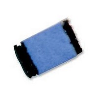
Y162410R0000C9R Vishay, Y162410R0000C9R Datasheet - Page 2

Y162410R0000C9R
Manufacturer Part Number
Y162410R0000C9R
Description
RESISTOR, METAL FOIL, 10OHM, 200mW, 0.25%
Manufacturer
Vishay
Series
VSMPr
Datasheet
1.Y162410R0000C9R.pdf
(4 pages)
Specifications of Y162410R0000C9R
Resistance
10ohm
Resistance Tolerance
± 0.25%
Power Rating
200mW
Voltage Rating
1.41V
Resistor Element Material
Metal Film
Temperature Coefficient
± 0.2ppm/°C
Lead Free Status / RoHS Status
Lead free / RoHS Compliant
**As shown + 0.01Ω to allow for measurement errors at low values.
***Land Pattern Dimensions are per IPC-782
Document Number: 63060
Revision: 26-Sep-05
SALES
• GERMANY/CZECH REPUBLIC/AUSTRIA: foilsales.eucentral@vishay.com
TABLE 4 - ENVIRONMENTAL PERFORMANCEPECIFICATIONS
Thermal Shock
Low Temperature Operation
Short Time Overload
High Temperature Exposure
Resistance to Soldering Heat
Moisture Resistance
Load Life Stability +70°C for 2000 hours
Maximum Working Voltage (V)
TABLE 5 - DIMENSIONS AND LAND PATTERN in inches (millimeters)
TABLE 2 - LOAD LIFE STABILITY
CHIP SIZE
0805
1206, 1506
2010
2512
CHIP
SIZE
0805
1206
1506
2010
2512
(*)
(*)
• AMERICAS: foilsales.usa@vishay.com
(+70°C FOR 2000 HOURS)
± 0.005 (0.13)
0.080 (2.03)
0.126 (3.2)
0.150 (3.81)
0.198 (5.03)
0.249 (6.32)
TCR of ± 0.2 ppm/°C and Load Life Stability of ± 0.005%
Z Foil Wrap Around Surface Mount Chip Resistor with
T
Uncoated
Ceramic
L
For technical questions in Asia/Japan/Europe/Africa/Israel, contact: foilsupport2@vishay.com
TEST
MAXIMUM ΔR LIMITS
± 0.005% at 100 mW
± 0.01% at 200 mW
± 0.005% at 150 mW
± 0.01% at 300 mW
± 0.005% at 200 mW
± 0.01% at 500 mW
± 0.005% at 500 mW
± 0.01% at 750 mW
Bottom View for Mounting
± 0.005 (0.13)
0.050 (1.27)
0.062 (1.57)
0.062 (1.57)
0.097 (2.46)
0.127 (3.22)
For technical questions in the Americas, contact: foilsupport1@vishay.com
D
W
L
VSMP Series (0805, 1206, 1506, 2010, 2512)
• ASIA/JAPAN: foilsales.asia@vishay.com
(*)
(*)
(*)
(*)
THICKNESS
• FRANCE/SWITZERLAND/SOUTHERN EUROPE: foilsales.eusouth@vishay.com
0.025 (0.64)
0.025 (0.64)
0.025 (0.64)
0.025 (0.64)
0.025 (0.64)
MAXIMUM
W
± 0.005 (0.13)
0.015 (0.38)
0.020 (0.50)
0.020 (0.50)
0.025 (0.64)
0.032 (0.81)
(*)
Note: See table 1
TABLE 3 - SPECIFICATIONS
CHIP SIZE
0805
1206
1506
2010
2512
CHARACTERISTIC E
VSMP2010 and VSMP2512 data are preliminary, for more
details please contact Application Engineering using the e-mail
addresses in the footer below.
D
MIL-PRF-55342 H
(*)
(*)
ΔR LIMITS
Recommended Land Pattern
± 0.1%
± 0.1%
± 0.1%
± 0.1%
± 0.2%
± 0.2%
± 0.5%
Z
G
POWER (mW)
0.122 (3.10)
0.175 (4.4)
0.199 (5.05)
0.247 (6.27)
0.291 (7.40)
• UK/HOLLAND/SCANDINAVIA: foilsales.eunorth@vishay.com
MAXIMUM
MAXIMUM
at +70°C
200
300
300
500
750
Z***
(*)
(*)
PxR
Vishay Foil Resistors
X
RESISTANCE
0.028 (0.70)
0.059 (1.5)
0.083 (2.1)
0.115 (2.92)
0.150 (3.8)
RANGE (Ω)
10 to 12K
10 to 30K
10 to 40K
10 to 100K
10 to 150K
MINIMUM
G***
Footprint
• ISRAEL: foilsales.israel@vishay.com
ΔR LIMITS**
MAXIMUM
± 0.01%
± 0.01%
± 0.01%
± 0.02%
± 0.01%
± 0.02%
± 0.01%
VSMP
www.vishay.com
WEIGHT (mg)
0.050 (1.27)
0.071 (1.80)
0.071 (1.80)
0.103 (2.63)
0.127 (3.22)
MAXIMUM
MAXIMUM
X***
6
11
12
27
40
2


