WSC25152R600FEA Vishay, WSC25152R600FEA Datasheet
WSC25152R600FEA
Specifications of WSC25152R600FEA


Related parts for WSC25152R600FEA

WSC25152R600FEA Summary of contents
Page 1
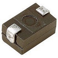
... Historical Part Numbering example: WSC-1 0.7 R86 WSC-1 HISTORICAL MODEL Note (4) WSC2515 only * Pb containing terminations are not RoHS compliant, exemptions may apply ** Please see document “Vishay Material Category Policy”: Document Number: 30102 For technical questions, contact: Revision: 17-Feb-11 Wirewound Resistors, FEATURES • All welded construction • ...
Page 2
... WSC, WSN Vishay Dale DIMENSIONS in inches (millimeters GLOBAL MODEL L H 0.200 ± 0.020 0.096 ± 0.015 WSC01/2 (5.08 ± 0.508) (2.44 ± 0.381) 0.250 ± 0.020 0.110 ± 0.015 WSC0001 (6.35 ± 0.508) (2.79 ± 0.381) 0.250 ± 0.020 0.110 ± 0.015 WSC2515 (6.35 ± ...
Page 3
... Vishay product could result in personal injury or death. Customers using or selling Vishay products not expressly indicated for use in such applications their own risk and agree to fully indemnify and hold Vishay and its distributors harmless from and against any and all claims, liabilities, expenses and damages arising or resulting in connection with such use or sale, including attorneys fees, even if such claim alleges that Vishay or its distributor was negligent regarding the design or manufacture of the part ...