E3S-BR61 Omron, E3S-BR61 Datasheet - Page 9
E3S-BR61
Manufacturer Part Number
E3S-BR61
Description
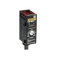
Photoelectric Sensors - Industrial 1M RETRO NPN VERT
Manufacturer
Omron
Type
Photoelectric Sensorr
Series
E3S-Br
Datasheet
1.E3S-BT61-L.pdf
(10 pages)
Specifications of E3S-BR61
Features
Light ON / Dark ON
Height
44.8 mm
Length
30.2 mm
Maximum Operating Temperature
+ 55 C
Minimum Operating Temperature
- 25 C
Operating Supply Voltage
10 V to 30 V
Width
21.4 mm
Sensing Distance
1000 mm
Output Configuration
NPN
Sensing Method
Retroreflective, Polarized
Sensing Object
Mirror
Sensing Light
Red
Mounting Type
Screw, Vertical
Current - Supply
25mA
Voltage - Supply
10 V ~ 30 V
Package / Case
Module, Pre-Wired
Lead Free Status / Rohs Status
Lead free / RoHS Compliant
Available stocks
Company
Part Number
Manufacturer
Quantity
Price
Company:

Part Number:
E3S-BR61
Manufacturer:
OMRON
Quantity:
524


J MUTUAL INTERFERENCE FILTER
Operation
J SENSITIVITY ADJUSTMENT
Unlike conventional photoelectric sensors, the variation in the sensitivity of E3S photoelectric sensors is minimal. This means the
sensitivity can be adjusted on only a single photoelectric sensor, and then the adjusters on the other photoelectric sensors can be set to
the same scale position. There is no need to adjust the sensitivity of each photoelectric sensor individually.
E
Steps
Function
Sensing
condition
Sensitivity
adjuster
Indicators
39
-E
8
Step 1
Determine Position A
Place target at the desired sensing
distance. Set sensitivity adjuster to the
minimum scale position and gradually
increase sensitivity by turning the
sensitivity adjuster clockwise until the
Light Incident indicator (red LED)
turns ON. Position A designates the
point at which the LED has turned ON.
(0.08)
2.1
(0.64)
Photoelectric sensor
OFF
16.2
Min
STABILITY
(green)
Target
Max
ON
LIGHT
(red)
Step 2
Determine Position B
Remove the target. Starting from the
maximum scale position, gradually
decrease sensitivity by turning the
sensitivity adjuster counterclockwise
until the Light Incident indicator (red
LED) is OFF. Position B designates
the point at which the LED has turned
OFF.
OFF
Photoelectric sensor
STABILITY
(green)
Min
J MOUNTING ADAPTER PLATE
E
39
10
-L
61
OFF
Target
Max
LIGHT
(red)
(0.57)
14.5
Step 3
Adjust to optimum setting
Set the sensitivity indicator to the
position between Positions A and B (in
some cases, Positions A and B are
opposite of the above example). The
photoelectric sensor will then work
normally if the stability indicator
(green) is lit with and without the
target. If it is not lit, stable operation
cannot be expected, in which case a
different detection method should be
applied.
Photoelectric sensor
ON
Min
28 (1.10)
STABILITY
(green)
Max
Target
OFF
(0.09)
2.2
(0.10)
2.5
LIGHT
(red)
Related parts for E3S-BR61
Image
Part Number
Description
Manufacturer
Datasheet
Request
R

Part Number:
Description:
DETECTOR ONLY FOR E3S-BT31
Manufacturer:
Omron
Datasheet:
Part Number:
Description:
RECEIVER FOR E3S-BT81 PHOTO
Manufacturer:
Omron
Datasheet:
Part Number:
Description:
EMITTER ONLY FOR E3S-BT81
Manufacturer:
Omron
Datasheet:
Part Number:
Description:
SENSOR PHOTOELECTRIC CUSTOM
Manufacturer:
Omron
Datasheet:
Part Number:
Description:
SENSOR PHOTOELECTRIC CUSTOM
Manufacturer:
Omron
Datasheet:
Part Number:
Description:
SENSOR PHOTOELECTRIC CUSTOM
Manufacturer:
Omron
Datasheet:

Part Number:
Description:
SENSOR PHOTOELECTRIC CUSTOM
Manufacturer:
Omron
Datasheet:
Part Number:
Description:
2M SEP PNP HORZ
Manufacturer:
Omron
Datasheet:
Part Number:
Description:
2M SEP NPN HORZ
Manufacturer:
Omron
Datasheet:
Part Number:
Description:
2M SEP NPN VERT
Manufacturer:
Omron
Datasheet:

Part Number:
Description:
G6S-2GLow Signal Relay
Manufacturer:
Omron Corporation
Datasheet:
Part Number:
Description:
Compact, Low-cost, SSR Switching 5 to 20 A
Manufacturer:
Omron Corporation
Datasheet:
Part Number:
Description:
Manufacturer:
Omron Corporation
Datasheet: