DECB33J101KC4B Murata, DECB33J101KC4B Datasheet - Page 29
DECB33J101KC4B
Manufacturer Part Number
DECB33J101KC4B
Description
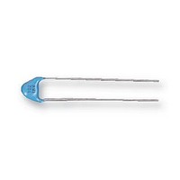
CAPACITOR, 100PF 6000V CAPACITOR, 100PF 6000V
Manufacturer
Murata
Type
Ceramic Discr
Series
DEr
Datasheet
1.DECB33J101KC4B.pdf
(72 pages)
Specifications of DECB33J101KC4B
Tolerance (+ Or -)
10%
Voltage
6300VDC
Temp Coeff (dielectric)
B
Operating Temp Range
-25C to 85C
Mounting Style
Through Hole
Construction
Radial
Lead Spacing (nom)
10mm
Product Length (mm)
Not Requiredmm
Product Depth (mm)
7mm
Product Height (mm)
Not Requiredmm
Product Diameter (mm)
9mm
Lead Diameter (nom)
0.6mm
Seated Plane Height
12mm
Capacitance
100pF
Package / Case
Not Required
Voltage Rating, Dc
6300V
Capacitor Dielectric Type
CERAMIC DISC AND PLATE
Tolerance,
10%
Tolerance, -
10%
Temp, Op. Max
85(DEGREE C)
Temp, Op.
ROHS COMPLIANT
Lead Free Status / RoHS Status
Compliant
Available stocks
Company
Part Number
Manufacturer
Quantity
Price
Company:

Part Number:
DECB33J101KC4B
Manufacturer:
MURATA
Quantity:
33 000


!Note
• This PDF catalog is downloaded from the website of Murata Manufacturing co., ltd. Therefore, it’s specifications are subject to change or our products in it may be discontinued without advance notice. Please check with our
• This PDF catalog has only typical specifications because there is no space for detailed specifications. Therefore, please approve our product specifications or transact the approval sheet for product specifications before ordering.
sales representatives or product engineers before ordering.
!Note
Operating and Storage Environment
1. Vibration and Impact
2. Soldering
3. Bonding, Resin Molding and Coating
Vibration and Impact
FAILURE TO FOLLOW THE ABOVE CAUTIONS MAY
RESULT, WORST CASE, IN A SHORT CIRCUIT
AND CAUSE FUMING OR PARTIAL DISPERSION
WHEN THE PRODUCT IS USED.
The insulating coating of capacitors does not form a
perfect seal; therefore, do not use or store
capacitors in a corrosive atmosphere, especially
where chloride gas, sulfide gas, acid, alkali, salt
or the like are present. And avoid exposure to
moisture. Before cleaning, bonding, or molding this
product, verify that these processes do not affect
product quality by testing the performance of a
cleaned, bonded or molded product in the intended
Do not expose a capacitor or its leads to excessive
shock or vibration during use.
Do not expose a capacitor or its leads to
excessive shock or vibration during use.
When soldering this product to a PCB/PWB, do not
exceed the solder heat resistance specifications of
the capacitor. Subjecting this product to excessive
heating could melt the internal junction solder and
may result in thermal shocks that can crack the
ceramic element.
When soldering capacitor with a soldering iron, it
should be performed in the following conditions.
Before bonding, molding or coating this product,
!Caution (Storage and Operating Condition)
!Caution (Soldering and Mounting)
verify that these processes do not affect the
quality of capacitor by testing the performance of
!Caution (Handling)
Temperature of iron-tip: 400 degrees C. max.
Soldering iron wattage: 50W max.
Soldering time: 3.5 sec. max.
• Please read rating and !CAUTION (for storage, operating, rating, soldering, mounting and handling) in this catalog to prevent smoking and/or burning, etc.
• This catalog has only typical specifications because there is no space for detailed specifications. Therefore, please approve our product specifications or transact the approval sheet for product specifications before ordering.
Safety Recognized Ceramic Capacitors !Caution
FAILURE TO FOLLOW THE ABOVE CAUTIONS MAY
RESULT, WORST CASE, IN A SHORT CIRCUIT
AND CAUSE FUMING OR PARTIAL DISPERSION
WHEN THE PRODUCT IS USED.
FAILURE TO FOLLOW THE ABOVE CAUTIONS MAY
RESULT, WORST CASE, IN A SHORT CIRCUIT
AND CAUSE FUMING OR PARTIAL DISPERSION
WHEN THE PRODUCT IS USED.
equipment. Store the capacitors where the
temperature and relative humidity do not exceed -10
to 40 degrees centigrade and 15 to 85%.
Use capacitors within 6 months after delivery.
the bonded, molded or coated product in the
intended equipment.
In case the amount of applications,
dryness/hardening conditions of adhesives and
molding resins containing organic solvents
(ethyl acetate, methyl ethyl ketone, toluene, etc.)
are unsuitable, the outer coating resin of a
capacitor is damaged by the organic solvents and
it may result, worst case, in a short circuit.
The variation in thickness of adhesive, molding
resin or coating may cause outer coating resin
cracking and/or ceramic element cracking of a
capacitor in a temperature cycling.
C85E.pdf
27
08.10.29
5
Related parts for DECB33J101KC4B
Image
Part Number
Description
Manufacturer
Datasheet
Request
R

Part Number:
Description:
Murata Microblower 20x20 DCDC Driver Board - Samples Only
Manufacturer:
Murata
Part Number:
Description:
357-036-542-201 CARDEDGE 36POS DL .156 BLK LOPRO
Manufacturer:
Murata
Datasheet:
Part Number:
Description:
Manufacturer:
Murata
Datasheet:
Part Number:
Description:
Manufacturer:
Murata
Datasheet:
Part Number:
Description:
Manufacturer:
Murata
Datasheet:
Part Number:
Description:
Manufacturer:
Murata
Datasheet:
Part Number:
Description:
Manufacturer:
Murata
Datasheet:
Part Number:
Description:
Manufacturer:
Murata
Datasheet:
Part Number:
Description:
Manufacturer:
Murata
Datasheet:
Part Number:
Description:
BLM21BD751SN1On-Board Type (DC) EMI Suppression Filters
Manufacturer:
Murata
Datasheet:
Part Number:
Description:
BLM15AG100SN1On-Board Type (DC) EMI Suppression Filters
Manufacturer:
Murata
Datasheet:
Part Number:
Description:
NFE31PT222Z1E9On-Board Type (DC) EMI Suppression Filters
Manufacturer:
Murata
Datasheet:
Part Number:
Description:
Chip Coil
Manufacturer:
Murata
Datasheet:
Part Number:
Description:
Chip Coil
Manufacturer:
Murata
Datasheet: