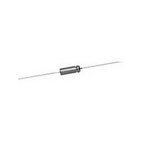
138D106X9050C2 Vishay, 138D106X9050C2 Datasheet - Page 6

138D106X9050C2
Manufacturer Part Number
138D106X9050C2
Description
CAPACITOR TANT 10UF, 50V, 8OHM, AXIAL
Manufacturer
Vishay
Datasheet
1.138D106X9050C2.pdf
(8 pages)
Specifications of 138D106X9050C2
Esr
8Ohm
Capacitance
10uF
Tolerance (+ Or -)
10%
Voltage
50VDC
Mounting Style
Through Hole
Operating Temp Range
-55C to 85C
Construction
Axial
Dcl
1uA
Seal
Hermetic
Insulation
Sleeved
Polarity
Polar
Failure Rate
Not Required
Product Length (mm)
15.45mm
Product Depth (mm)
Not Requiredmm
Product Height (mm)
Not Requiredmm
Product Diameter (mm)
5.56mm
Capacitance Tolerance
± 10%
Voltage Rating
50VDC
Capacitor Case Style
Axial
No. Of Pins
2
Operating Temperature Range
-55°C To +85°C
Capacitor Mounting
Through Hole
Termination Type
Axial Leaded
Rohs Compliant
No
Lead Free Status / RoHS Status
Not Compliant
138D
Vishay
PERFORMANCE CHARACTERISTICS
1.
2.
3.
3.1
4.
www.vishay.com
6
TYPICAL CURVES OF IMPEDANCE AS A FUNCTION OF FREQUENCY AT VARIOUS TEMPERATURES
100
200
10
1.0
0.2
Operating Temperature: Capacitors are designed to
operate over the temperature range of - 55 °C to
+ 125 °C.
DC Working Voltage: The DC working voltage is the
maximum operating voltage for continuous duty at the
rated temperature.
Surge Voltage: The surge DC rating is the maximum
voltage to which the capacitors should be subjected
under any conditions. This includes transients and
peak ripple at the highest line voltage. The surge
voltage of capacitors rated below 150 V is 115 % of the
rated DC working voltage. The surge voltage of
capacitors rated at 150 V DC is 165 volts.
Surge Voltage Test: Capacitors shall withstand the
surge voltage test applied through a 1000 ± 10 %
resistor in series with the capacitor and voltage source
at the rate of one-half minute on, four and one-half
minutes off, for 1000 successive test cycles at + 85 °C
or + 125 °C.
Capacitance Tolerance: The capacitance of all
capacitors shall be within the specified tolerance limits
of the nominal rating.
100
WORKING
VOLTAGE
+ 85 °C
UP TO
(V)
10
15
20
25
30
6
8
1K
Wet Tantalum Capacitors Sintered Anode T
“K” Case 120 µF, 25 V Capacitors
125 °C
WORKING
VOLTAGE
+ 125 °C
(V)
AT
10
13
15
20
4
5
7
FREQUENCY IN Hz
Hermetically-Sealed with True Glass-to-Tantalum Seal
10K
+ 85
WORKING
VOLTAGE
+ 85 °C
For technical questions, contact:
UP TO
°C
100K
100
125
150
(V)
35
50
60
75
+ 25
- 20
- 40
°C
- 55
°C
WORKING
VOLTAGE
1M
+ 125 °C
°C
100
(V)
AT
22
30
40
50
70
85
10M
tantalum@vishay.com
200
100
10
1.0
0.2
4.1
5.
6.
6.1
6.2
100
Capacitance measurements shall be made by the
bridge method at or referred to, a frequency of 120 Hz
at a temperature of + 25 °C. A polarizing voltage shall
be used of such magnitude that there shall be no
reversal of polarity due to the AC component. The
maximum AC voltage will be 1 volt rms applied during
measurement.
Capacitance Change With Temperature: The
capacitance change with temperature shall not exceed
the limits given in the Standard and Extended Ratings
Table for each capacitor.
Equivalent Series Resistance: Measurements shall
be made by the bridge method at or referred to, a
frequency of 120 Hz at a temperature of + 25 °C. A
polarizing voltage shall be used of such magnitude that
there shall be no reversal of polarity due to the AC
component. The maximum AC voltage will be 1 V
applied during measurement.
The equivalent series resistance shall not exceed the
maximum value in ohms listed in the Standard and
Extended Ratings Table for each capacitor.
The dissipation factor may be calculated from the
equivalent series resistance and capacitance values
as shown:
where:
DF = Dissipation Factor in %
R = ESR in ohms
C = Capacitance in µF
f = frequency in Hz
At 120 Hz, the above equation becomes:
DF
DF
ANTALEX
=
=
1K
2fRC
----------------- -
R C
-------------- -
13.26
10
“C” Case 10 µF. 100 V Capacitors
4
FREQUENCY IN Hz
®
10K
Capacitors
+125
°C
100K
Document Number: 40025
+ 85
Revision: 21-Jan-11
- 40
+ 25
- 20
°C
1M
- 55
°C
°C
°C
°C
10M
rms


