FL75L05 A Delta Electronics, FL75L05 A Datasheet - Page 3
FL75L05 A
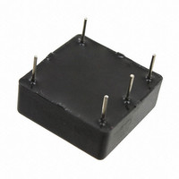
Manufacturer Part Number
FL75L05 A
Description
EMI FILTER 75VDC 5A T/H
Manufacturer
Delta Electronics
Series
DELPHIr
Specifications of FL75L05 A
Filter Type
Power Line
Voltage - Rated
75V
Current
5A
Inductance
-
Mounting Type
Through Hole
Termination Style
PCB Pins
Lead Free Status / RoHS Status
Supplier Unconfirmed


DS_FL75L07_11272006
THERMAL CONSIDERATIONS
Thermal management is an important part of the system
design. To ensure proper, reliable operation, sufficient
cooling of the power module is needed over the entire
temperature range of the module. Convection cooling is
usually the dominant mode of heat transfer.
Hence, the choice of equipment to characterize the
thermal performance of the power module is a wind
tunnel.
Thermal Testing Setup
Delta’s filter modules are characterized in heated
vertical wind tunnels that simulate the thermal
environments
equipment. This type of equipment commonly uses
vertically mounted circuit cards in cabinet racks in which
the power modules are mounted.
The
characterization setup. The filter module is mounted on
a test PWB and is vertically positioned within the wind
tunnel. The space between the neighboring PWB and
the top of the power module is 6.35mm (0.25”).
Thermal Derating
Heat can be removed by increasing airflow over the
module. Figure 4 shows maximum output is a function of
ambient temperature and airflow rate. To enhance
system reliability, the power module should always be
operated below the maximum operating temperature. If
the
temperature, reliability of the unit may be affected.
Figure 4: Wind tunnel test setup
Note: Wind Tunnel Test Setup Figure Dimensions are in millimeters and (Inches)
MEASURED BELOW
temperature
following
TEMPERATURE
AIR VELOCITY
AND AMBIENT
THE MODULE
FACING PWB
encountered
figure
exceeds
AIR FLOW
shows
the
in
PWB
50.8 (2.0”)
MODULE
the
maximum
10 (0.4”)
most
wind
electronics
module
tunnel
THERMAL CURVES
Figure 5: Temperature measurement location
The allowed maximum hot spot temperature is defined at 115
Figure 6: Output Current vs. Ambient Temperature and Air
Velocity @ Vin = 48V (Either Orientation)
8
7
6
5
4
3
2
1
0
25
Output Current (A)
FL75L07 A (Standard) Output Current vs. Ambient Temperature and Air Velocity
35
45
@ Vin = 48V (Either Orientation)
Convectio
300LFM
100LFM
200LFM
Natural
55
65
Ambient Temperature (℃)
75
℃
85
3
Related parts for FL75L05 A
Image
Part Number
Description
Manufacturer
Datasheet
Request
R

Part Number:
Description:
Delta Electronics, Inc. [ETHERNET 10BASE-T LAN FILTER MODULES]
Manufacturer:
Delta Electronics, Inc.
Datasheet:
Part Number:
Description:
Manufacturer:
Delta Electronics, Inc.
Datasheet:
Part Number:
Description:
Manufacturer:
Delta Electronics, Inc.
Datasheet:
Part Number:
Description:
Manufacturer:
Delta Electronics, Inc.
Datasheet: