PV32P253A01B00 Murata, PV32P253A01B00 Datasheet - Page 23
PV32P253A01B00
Manufacturer Part Number
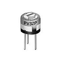
PV32P253A01B00
Description
Trimmer Resistors - Single Turn 25K OHM 6MM SGL TRN
Manufacturer
Murata
Type
Trimmerr
Datasheet
1.PV32P253A01B00.pdf
(59 pages)
Specifications of PV32P253A01B00
Resistance
25kohm
Power Rating
1/2W
Tolerance (+ Or -)
20%
Number Of Turns
1Turn
Technology
Cermet
Mounting Style
Through Hole
Termination Style
Pin
Operating Temp Range
-55C to 125C
Failure Rate
Not Required
Shaft Diameter (mm)
2.8mm
Product Diameter (mm)
6.6mm
Product Length (mm)
Not Requiredmm
Product Height (mm)
6mm
Product Depth (mm)
Not Requiredmm
Temperature Coefficient
±100
Tolerance
20 %
Operating Temperature Range
- 55 C to + 125 C
Product
Trimmer Resistors - Single Turn
Taper
Linear
Lead Free Status / RoHS Status
Compliant


!Note
• This PDF catalog is downloaded from the website of Murata Manufacturing co., ltd. Therefore, it’s specifications are subject to change or our products in it may be discontinued without advance notice. Please check with our
• This PDF catalog has only typical specifications because there is no space for detailed specifications. Therefore, please approve our product specifications or transact the approval sheet for product specifications before ordering.
sales representatives or product engineers before ordering.
!Note
1. Store in temperatures of -10 to +40 deg. C and
2. Do not store in or near corrosive gases.
3. Use within six months after delivery.
4. Open the package just before using.
5. Do not store under direct sunlight.
6. If you use the trimmer potentiometer in an
1. When using with partial load (rheostat), minimize
2. The maximum input voltage to a trimmer
1. Soldering
(1) Soldering conditions
(2) Cannot be soldered using the flow soldering
(3) The soldering iron should not come in contact
(4) Apply the appropriate amount of solder paste.
Notice (Operating and Storage Conditions)
relative humidity of 30-85%.
environment other than listed below, please
consult with a Murata factory representative prior
to using.
The trimmer potentiometer should not be used under
the following environmental conditions:
Notice (Rating)
the power depending on the resistance value.
potentiometer should not exceed (P•R)^1/2 or the
maximum operating voltage, whichever is smaller.
Notice (Soldering and Mounting)
Refer to the temperature profile.
If the soldering conditions are not
suitable, e.g., excessive time and/or excessive
temperature, the trimmer potentiometer may
deviate from the specified characteristics.
method. If you use the flow soldering method,
the trimmer potentiometer may not function.
with the case of the trimmer potentiometer. If
such contact does occur, the trimmer
potentiometer may be damaged.
If the amount of solder paste applied to the
land is insufficient, the required adhesive
strength cannot be obtained. If an excessive
amount of solder paste is applied, solder
bridging or flux overflow to the resistive
element surface can occur.
• Please read rating and !CAUTION (for storage, operating, rating, soldering, mounting and handling) in this catalog to prevent smoking and/or burning, etc.
• This catalog has only typical specifications because there is no space for detailed specifications. Therefore, please approve our product specifications or transact the approval sheet for product specifications before ordering.
2. Mounting
3. Cleaning
(1) Use our standard land dimension. Excessive land
(2) Do not apply excessive force, preferably 4.9N
(3) Do not warp and/or bend PC board to prevent
(4) In chip placers, the size of the cylindrical
(1) Corrosive gaseous atmosphere
(2) In liquid
(3) Dusty/dirty atmosphere
(4) Direct sunlight
(5) Static voltage nor electric/magnetic fields
(6) Direct sea breeze
(7) Other variations of the above
Isopropyl-alcohol and Ethyl-alcohol are applicable
solvents for cleaning. If you use any other types
of solvents, please consult with a Murata factory
representative prior to using.
area causes displacement due to the effect of the
surface tension of the solder. Insufficient
land area leads to insufficient soldering
strength of the chip.
max. (Ref. 500gf) when the trimmer potentiometer
is mounted to the PCB.
trimmer potentiometer from breakage.
pick-up nozzle should be outer dimension
2.5-3.0mm dia. and inner dimension
2.0-2.5mm dia.
(Ex. Chlorine gas, Hydrogen sulfide gas, Ammonia
gas, Sulfuric acid gas, Nitric oxide gas, etc.)
(Ex. Oil, Medical liquid, Organic solvent, etc.)
PVG3 Series Notice
R50E.pdf
21
08.8.26
4
Related parts for PV32P253A01B00
Image
Part Number
Description
Manufacturer
Datasheet
Request
R

Part Number:
Description:
Murata Microblower 20x20 DCDC Driver Board - Samples Only
Manufacturer:
Murata
Part Number:
Description:
357-036-542-201 CARDEDGE 36POS DL .156 BLK LOPRO
Manufacturer:
Murata
Datasheet:
Part Number:
Description:
Manufacturer:
Murata
Datasheet:
Part Number:
Description:
Manufacturer:
Murata
Datasheet:
Part Number:
Description:
Manufacturer:
Murata
Datasheet:
Part Number:
Description:
Manufacturer:
Murata
Datasheet:
Part Number:
Description:
Manufacturer:
Murata
Datasheet:
Part Number:
Description:
Manufacturer:
Murata
Datasheet:
Part Number:
Description:
Manufacturer:
Murata
Datasheet:
Part Number:
Description:
BLM21BD751SN1On-Board Type (DC) EMI Suppression Filters
Manufacturer:
Murata
Datasheet:
Part Number:
Description:
BLM15AG100SN1On-Board Type (DC) EMI Suppression Filters
Manufacturer:
Murata
Datasheet:
Part Number:
Description:
NFE31PT222Z1E9On-Board Type (DC) EMI Suppression Filters
Manufacturer:
Murata
Datasheet:
Part Number:
Description:
Chip Coil
Manufacturer:
Murata
Datasheet:
Part Number:
Description:
Chip Coil
Manufacturer:
Murata
Datasheet: