PJRAS3X1S01X Switchcraft Inc., PJRAS3X1S01X Datasheet - Page 244
PJRAS3X1S01X
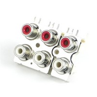
Manufacturer Part Number
PJRAS3X1S01X
Description
Phono (RCA) Connectors 3 POS RA SHLD PH JK
Manufacturer
Switchcraft Inc.
Datasheet
1.PJRAS3X1S01X.pdf
(333 pages)
Specifications of PJRAS3X1S01X
Gender
F
Number Of Ports
3Port
Body Orientation
Right Angle
Number Of Terminals
6
Contact Material
Copper Alloy
Number Of Contacts
6POS
Mounting Style
Through Hole
Termination Method
Solder
Operating Temp Range
-25C to 85C
Contact Plating
Silver
Color
Red, White, Yellow
Voltage Rating
34 Volts
Current Rating
2 Amps
Orientation
Right Angle
Shell Plating
Steel
Termination Style
Solder
Lead Free Status / RoHS Status
Compliant


FAX: 773 792 - 2129
SWITCHCRAFT, INC. 5555 N. Elston Ave. • Chicago, IL 60630
DESIGN MATERIALS AND FEATURES
Molded cable assemblies offer many advantages over
conventionally-fabricated cables:
• Improved wiring strain relief.
• Proper match of cable diameter to handle.
• Sealed junction: Less exposed area; less contamination
• Lower weight and smaller size.
• 100% shielding on selected types.
• Color to match/complement equipment decor.
• Legends, color codes, ribs, dot, customer logo/indicia
• All molded cables are 100% tested for continuity, shorts
• All Switchcraft
OEM COST SAVINGS
Molded cable assemblies generally cost less than your
in-house conventionally-fabricated assemblies. Specific
advantages are elimination of:
1. Your evaluation, ordering, incoming inspection, and
2. Your plant/equipment needs for in-house fabrication.
3. Your tooling/labor costs
4. Your production line QA/QC.
MOLDED CABLE RELIABILITY
In a series of OEM-conducted tests of Switchcraft versus
non-molded, fabricated cables, Switchcraft cables were shown
to be superior.
1. Fabricated cables broke at lower pull forces: OEM types – 24
2. Fabricated cables suffered broken wires at low pull-out force
Strengthened molded cable assemblies out-performed
fabricated assemblies, and in fact, the crimp molding process
makes it stronger than the wire itself.
SPECIAL ORDER ITEMS
• Customer Iogo
• Panel Relief Bushing. Specify panel thickness and exact
• Molded Cable Clamp Bands or Y-Junctions.
• Special Termination (see separate chart). Contact
TYPES OF PLASTICS
Thermoplastics used for molded cable assemblies, have
excellent electrical and mechanical properties, are economical,
convenient for molding, and can be provided in an array of
colors. They have electrical characteristics far higher than
required, and provide dimensional stability, abrasion and
abuse resistance, and can be molded with a smooth mirror-like
finish or matte or semi-matte finishes.
due to moisture, dust, dirt.
can be added.
and voltage breakdown (250 or 500V).
point on cable where bushing is to be installed. Standard
panel opening is .50" (12.7 mm) diameter. Double
flatted in panels up to .125" (3.18 mm) thick.
(Refer to page 258.)
Switchcraft for specials and provide complete details.
stocking of individual parts.
to 34 pounds, molded cables – 37.5 to 41 pounds
(molded cables did not break at terminations; the cable itself
broke about one to two feet back from the connector).
limits. Molded cables had cable breaks before cable pulled
out of the handle, in most instances. And this failure
occurred, as previously noted, at higher pull-out forces.
®
molded assemblies are UL recognized.
DIMENSIONS ARE FOR REFERENCE ONLY
WIRE AND CABLE
Switchcraft provides over 100 types of wire and cable from
which molded cable assemblies are manufactured. Basically,
30 different cables are used for standard tooling. There are no
additional charges where standard tooling exists.
Tooling is designed so cable entry openings on molded plastic
handles fit tightly to the outside diameter of the cable. The
tighter fit holds cable secure and is more resistant to abuse
than if a larger opening were used.
DESIGN AND FABRICATING TECHNIQUES
Switchcraft’s engineering staff is supported by a complete tool
and die making facility, as well as a fully equipped and staffed
molding department to fill all of Switchcraft’s plastic molding
requirements.
The molding department uses injection molders of
semi-automatic, multiple-cavity type to obtain high production
rates.
MANUFACTURING SEQUENCE (EXAMPLE)
Step 1: The 1-piece tip rod is firmly staked into the phone plug
finger assembly, making a complete and mechanically secure
assembly. (Refer to Figure 1) The staking process, using precision
manufactured parts, keeps the tip rod assembly from working
loose and causing mechanical and electrical problems later.
Step 2: Cable center conductor is soldered to tip rod; then the
tubular bridge sleeve is slid forward, bringing the cable shield in
contact with the circular notch around rear of tip rod assembly.
Step 3: Bridge sleeve is crimped tightly to tip rod assembly and
cable. Center conductor is completely isolated from potential
pulling strains, and shield makes a firm, low resistance
connection with plug sleeve.
Step 4: A dimensionally stable plastic handle/body of the
proper color, size and shape is molded into place. Features are
depressions for finger grip, cable entry opening customized to
cable diameter to minimize wear on cable, and handle/body
molded in one place.
From start to finish, Switchcraft’s molded cables are designed
and built with maximum quality and reliability. There is virtually
no limit to the type and characteristics of special molded cables
that Switchcraft can build to special order. For all special
orders, consult Switchcraft.
FIGURE 1: MOLDED CABLE MANUFACTURING STEPS
4. Complete
Body/Handle
Molded in Place
PATCH CORDS & MOLDED CABLE ASSEMBLIES
1. One Pc. Tip Rod
Assembly
(mm)
Inch
FOR 1/4" LITTEL PLUG
MOLDED CABLE ASSEMBLIES
MOLDED CABLE ASSEMBLIES
Cable Entry Opening - Custom
Selected to fit Cable Used
3. Crimped Bridge Sleeve
2. Center
Conductor
Termination
®
Bridge
Sleeve
239
Related parts for PJRAS3X1S01X
Image
Part Number
Description
Manufacturer
Datasheet
Request
R

Part Number:
Description:
CONN PLUG PHONE 1/4" 2POS RED
Manufacturer:
Switchcraft Inc.
Datasheet:

Part Number:
Description:
CONN PLUG 2-COND 1/4" PHONE SLD
Manufacturer:
Switchcraft Inc.
Datasheet:

Part Number:
Description:
CONN PLUG PHONE SILENT 2-COND
Manufacturer:
Switchcraft Inc.
Datasheet:

Part Number:
Description:
THICK PANEL/GOLD PLA
Manufacturer:
Switchcraft Inc.
Datasheet:

Part Number:
Description:
CONN JACK PHONE 1/4" 2POS CLOSED
Manufacturer:
Switchcraft Inc.
Datasheet:

Part Number:
Description:
CONN PHONE JACK 2COND 1/4" OPEN
Manufacturer:
Switchcraft Inc.
Datasheet:
Part Number:
Description:
CONN JACK PHONE 1/4" 2POS W/HDWR
Manufacturer:
Switchcraft Inc.
Datasheet:

Part Number:
Description:
CONN PLUG PHONE .206" 2POS BLACK
Manufacturer:
Switchcraft Inc.
Datasheet:
Part Number:
Description:
CONN PLUG PHONE 1/4" FLAT 2POS
Manufacturer:
Switchcraft Inc.
Datasheet:

Part Number:
Description:
CONN PLUG FLAT PHONE 1/4" 3-COND
Manufacturer:
Switchcraft Inc.
Datasheet:

Part Number:
Description:
PHONE T-JACK PANEL .25" STD SGL
Manufacturer:
Switchcraft Inc.
Datasheet:

Part Number:
Description:
CONN JACK PANEL 96POS W/O JACK
Manufacturer:
Switchcraft Inc.
Datasheet:
Part Number:
Description:
CONN PLUG PHONE .206" 3POS BLACK
Manufacturer:
Switchcraft Inc.
Datasheet:

Part Number:
Description:
CONN JACK 1/4" 3-COND IN-LINE
Manufacturer:
Switchcraft Inc.
Datasheet:

Part Number:
Description:
CONN PLUG AUDIO PHONE 3COND BLK
Manufacturer:
Switchcraft Inc.
Datasheet: