TRAPC7M1X Switchcraft Inc., TRAPC7M1X Datasheet - Page 69
TRAPC7M1X
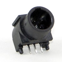
Manufacturer Part Number
TRAPC7M1X
Description
XLR Connectors RA TINI QG CONN RoH
Manufacturer
Switchcraft Inc.
Datasheet
1.TRAPC7M1X.pdf
(333 pages)
Specifications of TRAPC7M1X
Standard
Mini (Tiny) XLR
Gender
Male
Number Of Positions / Contacts
7
Termination Style
Solder
Mounting Style
PCB
Contact Plating
Tin
Color
Black
Contact Material
Brass
Voltage Rating
250 V
Current Rating
3 A
Orientation
Right Angle
Product Type
Connectors
Lead Free Status / RoHS Status
Compliant


64
w w w . s w i t c h c r a f t . c o m
CONNECTORS & RECEPTACLES
SLIM-LINE CONNECTORS
SLIM-LINE CONNECTORS
SL18 RECEPTACLES
Front of Panel Mount
SL MALE RECEPTACLES
SL FEMALE RECEPTACLES
SLIM-LINE CONNECTORS (continued)
Front of panel mount; 2 through 5 pins (male) or 2 through
5 contacts (female). Also 2-, 3- and 4-contact insert with
3 shunted (N.C.) contacts. Mounting locknut (Part Number
SL01), lockwasher (Part Number SL02), and flat washer
(Part Number SL03) supplied.
Part Number
Part Number
SL182M
SL183M
SL184M
SL185M
SL182F
SL183F
SL184F
SL185F
(17.7)
.696
Contacts
PANEL HOLE
Pins
2
3
4
5
2
3
4
5
Arrangements
SL183FS (typical)
Arrangements
DIMENSIONS ARE FOR REFERENCE ONLY
Contact
Pin
1
2
3
4
A
B
C
D
INSTALLING CABLE CLAMP ON INSERT
To install cable clamp on any insert:
1. Position insert approximately as shown in the diagram.
2. Hold clamp at approximately 30° angle (as shown). Place
3. Press center finger forward into slot and reduce angle of
Cable Clamp SL04
tip of clamp center finger into slot under molded ring “A”.
Note position of notch on insert in relation to slot.
clamp until clamp shoulders seat just ahead of molded
barrier on rear of insert “B”.
MOLDED
RING
“A”
INSERT
NOTCH
ON
(mm)
Note: Contact your Switchcraft Representative for price and delivery
Inch
PHONE: 773 792 - 2700
® Registered trademark of Switchcraft, Inc.
INSERT
“B”
CABLE
CLAMP
Related parts for TRAPC7M1X
Image
Part Number
Description
Manufacturer
Datasheet
Request
R

Part Number:
Description:
CONN PLUG PHONE 1/4" 2POS RED
Manufacturer:
Switchcraft Inc.
Datasheet:

Part Number:
Description:
CONN PLUG 2-COND 1/4" PHONE SLD
Manufacturer:
Switchcraft Inc.
Datasheet:

Part Number:
Description:
CONN PLUG PHONE SILENT 2-COND
Manufacturer:
Switchcraft Inc.
Datasheet:

Part Number:
Description:
THICK PANEL/GOLD PLA
Manufacturer:
Switchcraft Inc.
Datasheet:

Part Number:
Description:
CONN JACK PHONE 1/4" 2POS CLOSED
Manufacturer:
Switchcraft Inc.
Datasheet:

Part Number:
Description:
CONN PHONE JACK 2COND 1/4" OPEN
Manufacturer:
Switchcraft Inc.
Datasheet:
Part Number:
Description:
CONN JACK PHONE 1/4" 2POS W/HDWR
Manufacturer:
Switchcraft Inc.
Datasheet:

Part Number:
Description:
CONN PLUG PHONE .206" 2POS BLACK
Manufacturer:
Switchcraft Inc.
Datasheet:
Part Number:
Description:
CONN PLUG PHONE 1/4" FLAT 2POS
Manufacturer:
Switchcraft Inc.
Datasheet:

Part Number:
Description:
CONN PLUG FLAT PHONE 1/4" 3-COND
Manufacturer:
Switchcraft Inc.
Datasheet:

Part Number:
Description:
PHONE T-JACK PANEL .25" STD SGL
Manufacturer:
Switchcraft Inc.
Datasheet:

Part Number:
Description:
CONN JACK PANEL 96POS W/O JACK
Manufacturer:
Switchcraft Inc.
Datasheet:
Part Number:
Description:
CONN PLUG PHONE .206" 3POS BLACK
Manufacturer:
Switchcraft Inc.
Datasheet:

Part Number:
Description:
CONN JACK 1/4" 3-COND IN-LINE
Manufacturer:
Switchcraft Inc.
Datasheet:

Part Number:
Description:
CONN PLUG AUDIO PHONE 3COND BLK
Manufacturer:
Switchcraft Inc.
Datasheet: