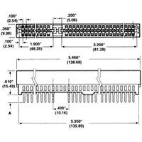
6-530843-5 TE Connectivity, 6-530843-5 Datasheet - Page 30

6-530843-5
Manufacturer Part Number
6-530843-5
Description
CARD EDGE CONNECTOR, 31POS
Manufacturer
TE Connectivity
Type
Card Edger
Datasheet
1.6-530843-5.pdf
(96 pages)
Specifications of 6-530843-5
Number Of Contacts
62POS
Number Of Contact Rows
2
Body Orientation
Straight
Contact Plating
Gold Over Nickel
Contact Material
Phosphor Bronze
Termination Method
Solder
Mounting Style
Through Hole
Product Height (mm)
15.49mm
Operating Temp Range
-55C to 85C
Pitch (mm)
2.54mm
Housing Material
Polyester
Housing Color
Black
Current Rating (max)
3/ContactA
Voltage Rating Max
400VAC
Contact Resistance Max
10
Peak Reflow Compatible (260 C)
No
Leaded Process Compatible
No
Rohs Compliant
No
Product Type
Connector
Product Series
Standard Edge II
Type Of Connector
Standard
Number Of Dual Positions
31
Post Type
Solder Post
Pcb Mounting Orientation
Vertical
Mounting Ears
Without
Pcb Mount Retention
Without
High Current
No
Termination Post Length (mm [in])
3.18 [0.125]
Solder Tail Contact Plating
Tin
Centerline (mm [in])
2.54 [0.100]
Retention Latch
Without
Positions Unloaded
None
Contact Plating, Mating Area, Material
Gold (30)
Contact Base Material
Phosphor Bronze
Underplate Material
Nickel
Ul Flammability Rating
UL 94V-0
Rohs/elv Compliance
ELV compliant, 5 of 6 Compliant
Lead Free Solder Processes
Wave solder capable to 240°C, Wave solder capable to 260°C, Wave solder capable to 265°C
Lead Free Status / RoHS Status
Not Compliant
30
Product Facts
Physical Properties:
Insulation Resistance—5000
megohms minimum.
Insertion/Withdrawal Force
(Daughter Card)—8 oz./2 oz.
[35.6 N/ 8.9 N] average contact pair
using .0620 [1.57] steel blade.
Insulator Body—Glass filled
thermoplastic, UL rating 94V-O. High
temp. plastic option is available; add
suffix M399 to part number.
Color—Black
Contacts—High strength copper alloy.
Contact Plating—.000050 [0.00127]
nickel underplate with .000030
[0.00076] gold in the mating area,
tin/lead on tails, .000100 [0.00254]
minimum
Electrical Properties:
Operation Voltage—600 VDC
(sea level)
Current Rating—3 Amperes
Initial Contact Resistance—
10 milliohms
Environmental Properties:
Operating Temperature—
-55˚C to +125˚C
Temperature Cycling—
MIL-STD-202 method 107
Vibration—MIL-STD-202 method 204
Related Product Data:
Daughter Card Edge Pattern—
page 57
Catalog 1654080
Issued 7-03
www.tycoelectronics.com
Recognized under the
Component Program
of Underwriters
Laboratories Inc.,
File No. E60980
Certified
by Canadian
Standards
Association,
File No. LR49571
Centered Mounting Ear
.125 [3.18] Thru Hole
[3.18]
.125
Dia.
Dimensions are in inches and
millimeters unless otherwise
specified. Values in brackets
are metric equivalents.
Centered Mounting Ear
4-40 Threaded Insert
Card Edge Connectors
(Solder Type, Board-to-Board)
Cantilever Series Connectors .100 x .200 [2.54 x 5.08] Centerline
Dip Solder Tails, .300 [7.62] Card Slot Depth
.128
[3.25] Dia.
#4-40
[2.54]
.100
Dimensions are shown for
reference purposes only.
Specifications subject
to change.
[2.54]
.100
No Mounting Ears
Mounting Styles
Typ.
.040±.003
[1.02±.08] Dia.
A
E
B
D
E
C
Dim E
Dim B
USA: 1-800-522-6752
Canada: 1-905-470-4425
Mexico: 01-800-733-8926
C. America: 52-55-5-729-0425
.125 [3.18] Thru Hole
Flush Mounting Ear
[0.51]
.020
[1.52]
.060
Typ. Dia.
[6.35]
[4.57]
.250
.180
[3.18] Dia.
.125
[5.08]
[9.40]
.200
.370
[15.49]
[6.35]
.250
.610
[3.68]
.145
South America: 55-11-3611-1514
Hong Kong: 852-2735-1628
Japan: 81-44-844-8013
UK: 44-141-810-8967
J
4-40 Threaded Insert
Flush Mounting Ear
.020±.010
[.51±.25]
[7.62]
.300
[5.08]
.200
Card Slot Depth
[6.35]
.250
Contact Gap


