MDM-9PCBR ITT, MDM-9PCBR Datasheet
MDM-9PCBR
Specifications of MDM-9PCBR
Available stocks


Related parts for MDM-9PCBR


MDM-9PCBR Summary of contents
Page 1
... No physical damage No loss of continuity > 1 sec No mechanical or electrical defects Insulation resistance > 100 megohms Shall be cable of mating and unmating, and meet contact resistance requirements 8 milliohms maximum 10 milliohms maximum 5 lb. minimum axial load Dimensions are shown in inches (millimeters). Dimensions subject to change. www.ittcannon.com 231 ...
Page 2
... Micro-D Metal Shell - .050" Contact Spacing How to Order MIL-C-83513 ordering information- pages 240 and 241 SERIES MDM (size 9-100): Liquid Crystal Ploymer (LCP) MDM (Combo Layout): Diallyl Phthalate insulator Material CONTACT ARRANGEMENTS 9-15-21-25-31-37-51-100 (standard) } 7C2, 24C42 (coaxial) or combination of 7P2, 24P4 (power) ...
Page 3
... Coaxial .320 (8.13 Size 25 Shell 5 Micro contact 2 Coax or 2 Power MDM Solid Uninsulated Type (L) #25 AWG gold plated copper Termination Code Length L61 .125 (3.18) L56 .150 (3.81) L57 .190 (4.83) L39 .250 (6.35) L58 .375 (9.52) L1 .500 (12.70) L14 ...
Page 4
... Micro-D Metal Shell - .050" Contact Spacing Shell Dimensions (Conforms to MIL-C-83513) Plug Receptacle Receptacle (MDM-100 only) Part Number Shell Size Max. Max. MDM-9P* .785 (19.94) .334 (8.48) MDM-9S* .785 (19.94) .402 (10.21) MDM-15P* .935 (23.75) .484 (12.29) MDM-15S* .935 (23.75) .552 (13.97) MDM-21P* 1 ...
Page 5
... MDM C .030 (0.76) TYP FULL R. PANEL REF. (TYP.) Figure 3 Edgeboard Mounting 1.805 +.005 -.000 .030 (45.85 ) .118 +.005 +0.13 -.000 -0.00 (0.76) TYP. (3.00 +0.13 -0. FULL R ...
Page 6
... Description Part Number Screw Lock Assembly 322-9500-000 Jackpost kit 320-9505-000 Mounting Bracket 90˚ MDM 015-9516-002 for 9 thru 37 Shell Sizes Mounting Bracket 90˚ MDM 015-9516-003 fo 51 Shell Size NOTES: Screw lock assembly (322-9500-000) can be used for front mounting only. Jackpot kit (320-9505-000) consists of two assmblies, shipped unassmbled ...
Page 7
... Mod Code Part Number Mod Code Part Number * * M5 320-9508-025 05 M15 320-9508-021 M6 320-9508-027 06 M16 320-9508-023 M2 320-9508-026 02 M12 320-9508-022 M3 320-9508-028 03 M13 320-9508-024 M7 320-9505-033 07 M17 320-9505-030 *Size 100 requires B1 size mounting holes. Dimensions are shown in inches (millimeters). Dimensions subject to change. www.ittcannon.com MDM .155 (3.94) MAX 237 ...
Page 8
... UNC-2A #4 LOCK WASHER .500 (12.70) MAX. .184 (4.70) MAX. MATING SIDE #4-40 UNC-2B INNER THD Jackpost - (P) Description Jackpost kit Mounting Bracket 90˚ MDM MATING FACE CONNECTOR SHOWN FOR REF. ONLY .031 + _ .003 PART HAS A .040 (1.02) #4-40 MATING (0. 0.08) UNC-2A ...
Page 9
... Simply mate the "Connectors Saver" to your unit and use the opposite side for your testing interface... less wear, less tear, less chansce of damage available in all seven standard MDM layouts. Mat- ing hardware is available and can be ordered either separately or included with the connector saver. ...
Page 10
... How to Order - ITT Cannon Part Number Nomenclature to MIL-C-83513 NOTES: (Specify when ordering, if necessary.) - For every Mil-Spec P/N, ITT has one corresponding part numbers. 1 Example: ITT P/N's MDM01- Tolerance on wire lengths-18", 36" and 72" long, +1.00"/-0.00" .5" and 1.00" + .200"/-.000" ...
Page 11
... Micro-D Metal Shell - .050" Contact Spacing How to Order - MIL-C-83513 Part Number Nomenclature NOTES: (Specify when ordering, if necessary.) - For every Mil-Spec P/N, ITT has one corresponding part numbers. 1 Example: ITT P/N's MDM01- Tolerance on wire lengths-18", 36" and 72" long, +1.00"/-0.00" .5" and 1.00" + .200"/-.000" For space application, connector shell finish must be " ...
Page 12
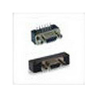
... M83513/5-17 (Size 100) No letter - none NOTE: Back molding material - Epoxy Hysol #MG40FS MDM-PCB MDM-PCB connectors are available in 8 shell sizes with 9 to 100 contacts. Terminations may be straight (BS 90û (BR, CBR) board thickness. Jackpost mounting for use with locking hardware is also available. ...
Page 13
... MDM-31PBS* 2.040 (51.82) 1.800 (45.72) MDM-31SBS* 2.040 (51.82) 1.800 (45.72) MDM-37PBS* 2.340 (59.44) 2.100 (53.34) MDM-37SBS* 2.340 (59.44) 2.100 (53.34) MDM-51PBS* 2.270 (67.66) 2.000 (50.80) MDM-51SBS* 2.270 (67.66) 2.000 (50.80) MDM-100PBS* 3.070 (77.98) 2.800 (71.12) MDM-100SBS* 3.070 (77.98) 2.800 (71.12) *For jackpost, add letter "P" or "M7" for sizes 9-51, "M17" for size 100. ...
Page 14
... MDM-25PBR* 1.790 (45.47) MDM-25SBR* 1.790 (45.47) MDM-31PBR* 2.040 (51.82) MDM-31SBR* 2.040 (51.52) MDM-37PBR* 2.340 (59.44) MDM-37SBR* 2.340 (59.44) MDM-51PBR* 1.875 (47.63) MDM-51SBR* 1.875 (47.63) *For jackpost, add letter "P" or "M7" for sizes 9-51, "M17" for size 100. .186 (4.72) MAX ...
Page 15
... Contacts View Y All Termination Configurations .100 (2.54) x .100 (2.54) Grid Pattern, Offset .050 (1.27). Part Number A By Shell Size Max .005 (.013) MDM-9PCBR* .785 (19.94) .565 (14.35) MDM-9SCBR* .785 (19.94) .565 (14.35) MDM-15PCBR* .935 (23.75) .715 (18.16) MDM-15SCBR* .935 (23.75) ...
Page 16
... Plug Coaxial Contacts Power Contacts MDM Coaxial The MDM Metal Shell Connectors have been tooled in several coaxial layouts and offer the versatility of combin- ing coaxial and signal lines in the same connector. Any modifications to these layouts or new requirements, please consult the factory. For ordering information see page 232 ...
Page 17
... See page 233. CONTACT TYPE P - Pin S - Socket Standard Wire Termination Codes ITT Cannon can also terminate a wide variety of stranded or solid wire directly to MICRO-D contacts, which is often desirable in high density arrangements. MICRO-D connectors can also be custom harnessed to meet any customer requirement of single or multiple connectors. Pigtail lead and harness description must be given by the customer. A typical description would be: .5" ...