5414105-1 TE Connectivity, 5414105-1 Datasheet - Page 2
5414105-1
Manufacturer Part Number
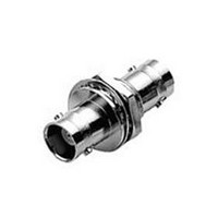
5414105-1
Description
RF/COAXIAL ADAPTER, BNC JACK-BNC JACK
Manufacturer
TE Connectivity
Type
BNC Adapterr
Datasheet
1.5414105-1.pdf
(34 pages)
Specifications of 5414105-1
Gender
RCP/RCP
Body Style
Straight
Body Plating
Nickel
Contact Plating
Gold
Contact Material
Phosphor Bronze
Product Depth (mm)
15.88mm
Product Length (mm)
36.07mm
Impedance
50Ohm
Connector Type
Intra Series Coaxial
Convert From Connector
BNC Coaxial
Convert From Gender
Jack
Convert To Connector
BNC Coaxial
Rohs Compliant
Yes
Rf Series
BNC
Side 1 Gender
Jack (Female)
Side 2 Gender
Jack (Female)
Adapter Style
Straight
Shell Plating
Nickel
Product Type
Adapter
Grade
Commercial
Pcb Mount Retention
Without
Body Shape
Vertical-Unflanged Base
Adapter Type
Jack-Jack
Body Insulation
Without
Sealed
No
Isolated
Yes
Dielectric Material
Polymethylpentene
Coupling Nut Material
Brass
Number Of Ports
1
Solder Terminal
Without
Surface Mountable
No
Panel Mount Retention
With
Panel Mount Retention Type
Bulkhead
Panel Attachment Style
Rear Mount, Front Mount
Connector Impedance (?)
50
Polarized
No
Center Contact Material
Phosphor Bronze
Center Contact Plating
Gold (50)
Connector Style
Jack
Government/industry Qualification
No
Rohs/elv Compliance
RoHS compliant, ELV compliant
Lead Free Solder Processes
Not relevant for lead free process
Rohs/elv Compliance History
Always was RoHS compliant
Lead Free Status / RoHS Status
Compliant


Electrical
Mechanical
Environmental
1
2
3
4
Catalog 1307191
Revised 3-07
www.tycoelectronics.com
Assembled to cable with polytetrafluorethylene dielectric.
Assembled to cable with polyethylene dielectric.
For Metal Threads
For Polyester Threads
Impedance, Nom.
(Ohms)
Working Voltage
(Volts RMS)
Contact Resistance
(Milliohms)
Initial Insulation Resistance
(Megohms)
Dielectric Withstanding
Voltage (VAC)
Corona Level at 70,000 ft.
(Volts, RMS)
RF Leakage, Max.
(dB)
RF Insertion Loss,
Max. (dB)
Frequency Range
(GHz)
VSWR in Frequency
Range Max.
Force to Engage (lbs. [N])/couple,
(in-lbs. [N-M]) max.
Coupling Nut Retention,
Min. N [lbs.]
Cable Retention,
N [lbs.]
Durability (Cycles)
Jam Nut Mounting Torque,
Max. [N•m] (in. lbs.)
Temperature Range,
Operating (C°)
Vibration
Physical Shock
Thermal Shock
Moisture
Resistance
Salt Spray
Product
Specification
Characteristics
Dimensions are in millimeters
and inches unless otherwise
specified. Values in brackets
are standard equivalents.
Cond. G, 50 G’s Cond. G, 50 G’s
MIL-STD-202
MIL-STD-202
MIL-STD-202
MIL-STD-202
MIL-STD-202
(MIL Type)
Method 204
Method 213
Method 107
Method 106
Method 101
13.3/11.12
(RG58C/U)
108-12002
266.9 [60]
-65 to +85
Inner: 1.5
Outer: 0.3
Cond. B
Cond. B
Single
Crimp
[3/2.5]
0-2.5
444.8
[100]
5000
1500
1.35
[2.8]
500
375
500
50
—
—
25
RF Coax Connectors
BNC Connectors (50 ohm/75 ohm) Performance Specifications
MIL-STD-202
MIL-STD-202
MIL-STD-202
MIL-STD-202
MIL-STD-202
Category B
(MIL Type)
-65 to +165
Method 204
Method 213
Method 107
Method 106
Method 101
-55 to +85
13.3/11.12
(RG58C/U)
108-12020
266.9 [60]
Outer: 0.2
O Crimp
Inner: 1.5
2-3 GHz
Cond. B
Cond. B
[3/2.5]
-55 at
3 GHz
0.2 at
444.8
[100]
5000
1500
1.30
[2.8]
500
375
500
0-4
50
25
2
1
MIL-STD-202
MIL-STD-202
MIL-STD-202
MIL-STD-202
MIL-STD-202
Dimensions are shown for
reference purposes only.
Specifications subject
to change.
Method 204
Method 213
Method 107
Method 106
Method 101
-65 to +165
(RG58C/U)
177.9 [40]
Outer: .20
Inner: 1.5
13.3/.028
Straight
2-3 GHz
Cond. B
Cond. G
Cond. B
Solder
Clamp
[3/2.5]
-55 at
3 GHz
0.2 at
444.8
[100]
5000
1500
1.30
[2.8]
500
375
0-4
500
—
50
25
Right-Angle
MIL-STD-202
MIL-STD-202
MIL-STD-202
MIL-STD-202
MIL-STD-202
-65 to +165
Method 204
Method 213
Method 107
Method 106
Method 101
(RG58C/U)
177.9 [40]
Outer: .20
Inner: 1.5
13.3/.028
2-3 GHz
Cond. G
Cond. B
Cond. B
Solder
Clamp
[3/2.5]
-55 at
3 GHz
0.3 at
444.8
[100]
5000
1500
1.35
500
375
500
0-4
—
—
50
Cond. G, 100 G’s
& Hex Crimp
MIL-STD-1344
MIL-STD-1344
MIL-STD-1344
MIL-STD-1344
MIL-STD-1344
Commercial
Method 2005
Method 2004
Method 1003
Method 1002
Method 1001
USA: 1-800-522-6752
Canada: 1-905-470-4425
Mexico: 01-800-733-8926
C. America: 52-55-1106-0803
26.7/26.69
(RG58C/U)
108-12044
108-12047
266.9 [60]
-55 to +85
50 Ohms
Outer: 1.0
O Crimp
Inner: 2.0
2-3 GHz
Cond. III
Cond. A
Cond. B
[6/6.0]
Type II
-55 at
3 GHz
0.2 at
266.9
5000
1500
1.30
[2.8]
500
375
[60]
500
0-4
50
25
Cond. I, 100 G’s
& Hex Crimp
Commercial
MIL-STD-202
MIL-STD-202
MIL-STD-202
MIL-STD-202
MIL-STD-202
Method 204
Method 213
Method 107
Method 106
Method 101
26.7/26.69
(RG58C/U)
108-12095
266.9 [60]
-55 to +85
75 Ohms
Outer: 2.0
O Crimp
Inner: 2.0
1-2 GHz
Cond. B
Cond. B
0.15 at
[6/6.0]
-55 at
2 GHz
266.9
5000
1500
1.30
[2.8]
[60]
500
375
0-2
500
75
25
Cond. I or A, 50 G’s Cond. I, 100 G’s
Commercial PC
50 & 75 Ohms
South America: 55-11-2103-6000
Hong Kong: 852-2735-1628
Japan: 81-44-844-8013
UK: 44-8706-080-208
MIL-STD-202
Method 201A
MIL-STD-202
MIL-STD-202
MIL-STD-202
MIL-STD-202
Method 213
Method 107
Method 106
Method 101
Inner: 6/1.5
Outer: 3/0.2
108-12078
266.9 [60]
-55 to +85
(PCB Ret)
[2.8/1.4]
50 & 75
Cond. B
0-4 and
25
Board
5000
1500
500
0-2
500
—
—
—
—
—
—
3
/12
4
50 Ohm Jacks
Commercial
MIL-STD-202
MIL-STD-202
MIL-STD-202
MIL-STD-202
MIL-STD-202
Method 204
Method 213
Method 107
Method 106
Method 101
-65 to +165
108-12079
Inner: 2.75
Outer: 1.0
50 & 75
Cond. B
Cond. B
Solder
5000
1500
[2.8]
500
375
0-4
500
—
—
—
—
—
—
25
45
Related parts for 5414105-1
Image
Part Number
Description
Manufacturer
Datasheet
Request
R

Part Number:
Description:
Printers THERMAL PRINTER HS-SLEEVE MARKER
Manufacturer:
TE Connectivity


Part Number:
Description:
High Speed / Modular Connectors 30P HEADER ASSY
Manufacturer:
TE Connectivity
Datasheet:

Part Number:
Description:
High Speed / Modular Connectors REC 6X005P R/A LT B-PLANE HS3
Manufacturer:
TE Connectivity
Datasheet:

Part Number:
Description:
High Speed / Modular Connectors 2MM HM RCPT 50P R/A AU
Manufacturer:
TE Connectivity
Datasheet:

Part Number:
Description:
High Speed / Modular Connectors 2MM HM RCPT 50P R/A AU
Manufacturer:
TE Connectivity
Datasheet:


Part Number:
Description:
Manufacturer:
TE Connectivity
Datasheet:


Part Number:
Description:
Manufacturer:
TE Connectivity
Datasheet:

Part Number:
Description:
Manufacturer:
TE Connectivity
Datasheet:

Part Number:
Description:
Manufacturer:
TE Connectivity
Datasheet: