5225555-6 TE Connectivity, 5225555-6 Datasheet - Page 2
5225555-6
Manufacturer Part Number
5225555-6
Description
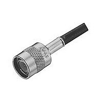
RF/COAXIAL, TNC PLUG, STR, 50OHM, CRIMP
Manufacturer
TE Connectivity
Type
TNCr
Specifications of 5225555-6
Gender
PL
Body Style
Straight
Terminate To
Coaxial Cable
Mounting Style
Cable
Termination
Crimp
Operating Temp Range
-65C to 125C
Operating Frequency
0 to 11
Body Plating
Nickel
Contact Plating
Gold
Contact Material
Phosphor Bronze
Insulation Material
Teflon
Product Length (mm)
34.93mm
Impedance
50Ohm
Connector Type
TNC Coaxial
Coaxial Termination
Crimp
Rg Cable Type
RG-142, 142A, 142B
Frequency Max
11GHz
Rohs Compliant
Yes
Angle
Straight
Application
True MIL
Cable Type
RG/U 142,142A,142B
Finish, Housing
Nickel
Material, Dielectric
TFE
Mating Type
Threaded
Primary Type
TNC
Voltage, Rating
500 V
Product Type
Connector - RF
Crimp Type
Dual
Weatherproof
Yes
Solder Terminal
Without
Grade
Military
Dielectric Material
Fluoropolymer
Panel Mount Retention
Without
Connector Impedance (?)
50
Coaxial Cable Termination Type
Crimp
Center Contact Plating
Gold
Coaxial Cable Type (rg/u Or Mfg.)
142, 142A, 142B
Government/industry Qualification
No
Rohs/elv Compliance
RoHS compliant, ELV compliant
Lead Free Solder Processes
Not relevant for lead free process
Rohs/elv Compliance History
Always was RoHS compliant
Applies To
Coaxial Cable
Lead Free Status / RoHS Status
Compliant


30
Specifications
Electrical
Mechanical
Environmental
1
2
Catalog 1307191
Revised 3-07
www.tycoelectronics.com
Assembled to cable with polytetrafluorethylene dielectric.
Assembled to cable with polyethylene dielectric.
Impedance, Nom.
(Ohms)
Working Voltage
(Volts RMS)
Contact Resistance
(Milliohms)
Initial Insulation Resistance
(Megohms)
Dielectric Withstanding
Voltage (VAC)
Corona Level at 70,000 ft.
(Picocoulombs)
RF Leakage, Max.
(dB)
RF Insertion Loss,
Max. (dB)
Frequency Range
(GHz)
VSWR in Frequency
Range Max.
Force to Engage/
Couple, lbs. [N]
Coupling Nut Retention,
Min. lbs. [N]
Cable Retention,
lbs. [N]
Durability (Cycles)
Jam Nut Mounting Torque,
Max. lbs. [N•m]
Temperature Range,
Operating (C°)
Vibration
Physical Shock
Thermal Shock
Moisture
Resistance
Salt Spray
Product
Specification
Characteristics
Dimensions are in millimeters
and inches unless otherwise
specified. Values in brackets
are standard equivalents.
Cond. G, (50 G’s)
@ 375 VRMS
MIL-STD-202
MIL-STD-202
MIL-STD-202
MIL-STD-202
MIL-STD-202
(MIL Type)
Method 204
Method 213
Method 107
Method 106
Method 101
60 [266.9]
-65 to +85
[44.5/8.9]
RG 58C/U
Inner: 1.5
Outer: 3
Cond. B
Cond. B
Single
[444.8]
Crimp
5 max.
5000
1500
[2.8]
1.35
10/2
500
100
500
0-4
—
—
—
50
25
RF Coax Connectors
TNC Connectors
Cond. I, (100 G’s)
@ 375 VRMS
MIL-STD-202
MIL-STD-202
MIL-STD-202
MIL-STD-202
MIL-STD-202
Category B
-65 to +165
(MIL Type)
Method 204
Method 213
Method 107
Method 106
Method 101
-55 to +85
108-12001
60 [266.9]
RG 58C/U
Outer: 0.2
O Crimp
Inner: 1.5
[8.9/8.9]
2-3 GHz
Cond. B
Cond. B
Cond. B
0.18 @
[444.8]
5 max.
9 GHz
60 @
5000
1500
0-11
[2.8]
500
100
500
1.3
2/2
50
25
2
1
Dimensions are shown for
reference purposes only.
Specifications subject
to change.
(Continued)
Cond. I, (100 G’s)
50 & 75 Ohm
& Hex Crimp
Commercial
@ 375 VRMS
MIL-STD-202
MIL-STD-202
MIL-STD-202
MIL-STD-202
MIL-STD-20
Method 213
Method 107
Method 106
Method 101
Method 204
[26.7/26.7]
108-12046
60 [266.9]
RG 58C/U
-55 to +85
Outer: 0.3
O Crimp
Inner: 2.0
2-3 GHz
Cond. B
Cond. A
Cond. B
[266.9]
5 max.
Type II
0.2 @
3 GHz
5000
1500
55 @
[2.8]
1.40
500
500
0-7
6/6
50
60
25
Cond. I, (100 G’s)
Commercial
MIL-STD-202
MIL-STD-202
MIL-STD-202
MIL-STD-202
MIL-STD-202
Method 201A
Method 213
Method 107
Method 106
Method 101
60 [266.9]
-55 to +85
Inner: 6.0
Outer: 3.0
(PCB Ret)
Cond. A
Cond. B
USA: 1-800-522-6752
Canada: 1-905-470-4425
Mexico: 01-800-733-8926
C. America: 52-55-1106-0803
5000
1500
PCB
[2.8]
500
0-4
500
—
—
—
—
—
—
—
50
25
Cond. I, (100 G’s)
Commercial
MIL-STD-202
MIL-STD-202
MIL-STD-202
MIL-STD-202
MIL-STD-202
-65 to +165
Method 204
Method 213
Method 107
Method 106
Method 101
Inner: 2.75
Outer: 1.0
Cond. B
Cond. B
Solder
Jacks
5000
1500
[2.8]
500
500
0-4
—
—
—
—
—
—
—
—
50
25
South America: 55-11-2103-6000
Hong Kong: 852-2735-1628
Japan: 81-44-844-8013
UK: 44-8706-080-208
MIL-STD-202
MIL-STD-202
MIL-STD-202
MIL-STD-202
MIL-STD-202
@ 375 VRMS
Semi-Rigid
-65 to +105
Method 202
Method 213
Method 107
Method 106
Method 101
108-12032
Outer: 0.2
Inner: 1.5
2-3 GHz
3-6 GHz
Cond. B
Cond. B
0.06 @
[444.8]
[266.9]
Cond. I
5 max.
[.023]
60 @
5000
1500
[2.8]
0-15
1.35
335
100
500
50
60
25
2
@ 375 VRMS
MIL-STD-202
MIL-STD-202
MIL-STD-202
MIL-STD-202
MIL-STD-202
Method 202
Method 213
Method 107
Method 106
Method 101
-65 to +165
Inner: 1.5
Outer: 0.2
2-3 GHz
Cond. B
Cond. B
Solder
Clamp
1.30 @
[444.8]
[178.0]
Cond. I
5 max.
0.2 @
3 GHz
4 GHz
[.023]
55 @
5000
1500
0-11
[2.8]
500
100
500
50
40
25
—
2
Related parts for 5225555-6
Image
Part Number
Description
Manufacturer
Datasheet
Request
R

Part Number:
Description:
Printers THERMAL PRINTER HS-SLEEVE MARKER
Manufacturer:
TE Connectivity


Part Number:
Description:
High Speed / Modular Connectors 30P HEADER ASSY
Manufacturer:
TE Connectivity
Datasheet:

Part Number:
Description:
High Speed / Modular Connectors REC 6X005P R/A LT B-PLANE HS3
Manufacturer:
TE Connectivity
Datasheet:


Part Number:
Description:
Manufacturer:
TE Connectivity
Datasheet:


Part Number:
Description:
Manufacturer:
TE Connectivity
Datasheet:

Part Number:
Description:
Manufacturer:
TE Connectivity
Datasheet:

Part Number:
Description:
Manufacturer:
TE Connectivity
Datasheet:


Part Number:
Description:
Manufacturer:
TE Connectivity
Datasheet: