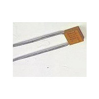
M39014/01-1473V AVX Corporation, M39014/01-1473V Datasheet - Page 9

M39014/01-1473V
Manufacturer Part Number
M39014/01-1473V
Description
Manufacturer
AVX Corporation
Datasheet
1.M3901401-1473V.pdf
(14 pages)
Specifications of M39014/01-1473V
Tolerance (+ Or -)
10%
Voltage
50VDC
Temp Coeff (dielectric)
X7R
Operating Temp Range
-55C to 125C
Mounting Style
Through Hole
Construction
Radial
Case Style
Molded
Failure Rate
M
Wire Form
Outside Bend Stndoff
Product Length (mm)
4.83mm
Product Depth (mm)
2.29mm
Product Height (mm)
4.83mm
Product Diameter (mm)
Not Requiredmm
Capacitance
.1uF
Package / Case
Not Required
Lead Free Status / RoHS Status
Not Compliant
MIL-PRF-39014/2Pin DIP
HOW TO ORDER
Military Type Designation: Styles CKR22, CKR23, CKR24
Dash Number Option: MIL-PRF-39014/22 (Add Appropriate Dash Number)
PACKAGING REQUIREMENTS
Packaging: MD01/MD02: 200 pcs/slide pack. See page 35.
CK = General purpose,
22 = Remaining two
R = Established
CKR22
ceramic dielectric,
fixed capacitors
Reliability parts
numbers identify
shape and
dimension
Style
MD03: 200 pcs per vial.
200 pcs per slide pack upon request.
Second
voltage-temperature coefficient.
Letter
Temperature Limits
G
H
R
X
with Reference to 25°C
Second letter identifies
C = -55ºC to +150ºC
B = -55ºC to +125ºC
Capacitance Change
First letter identifies
temperature range.
+30, -30ppm +30, -30ppm
+60, -60ppm +60, -60ppm
+15, -15%
+15, -15%
Voltage-
Voltage
No
BX
Note 1 = Leads centered within .005"
Note 2 = Angle shall be 95, +10, -5
Note 3 = .140 .020 inch (3.56 0.51mm) for
NOTE 1
SEE
.004
+15, -40%
+15, -25%
.012
Voltage
Rated
standard lead length; .170 .010 inch
(4.32 0.25mm) for optional longer
lead length.
L
.400 max.
NOTE 2
.035
SEE
.325
First two digits are the significant
figures of capacitance. Third digit
indicates the additional number
of zeros. For example, order
100,000 pF as 104. (For values
below 10pF use “R” in place of
decimal point, e.g., 1R5 = 1.5pF.)
Capacitance
.019 .004
.058 .012
104
60 TYP.
.015
MIN
MIL-PRF-39014
20
SIZE SPECIFICATIONS
H
1
CKR22
CKR23
CKR24
MAX.
T
Note 3
(.260 ±.020)
(.260 ±.020)
(.260 ±.020)
MAX.
See
H
Length
2
Capacitance
6.60
6.60
6.60
(L)
.010 MAX.
Tolerance
.019 .004
M = ±20%
D = ±.5pF
K = ±10%
F = ±1%
J = ±5%
K
(.128 ±.007)
(.155 ±.007)
(.283 ±.007)
Height
3.25
3.94
7.19
(H
1
Failure Rate Level
)
R (STD) (No X-ray)
S (STD) (X-ray)
AVX reserves the right to substi-
tute a lower failure rate part per
MIL-PRF-39014. Substitutability
for failure rate levels shall be as
follows:
M
P
M = 1% per 1000 hours
P = 0.1% per 1000 hours
R = 0.01% per 1000 hours
S = 0.001% per 1000 hours
4.45 max.
4.95 max.
8.13 max.
Dimensions: Millimeters (Inches)
Height
(.175)
(.195)
(.320)
Failure Rate
(H
2
Military
)
Note:
R
Failure Rate Level
Will Replace
Thickness
(.092 ±.006)
(.092 ±.006)
(.092 ±.006)
R, P, M, L
P, M, L
2.34
2.34
2.34
M,L
L
55


