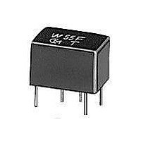
CFWLB455KG1Y-B0 Murata, CFWLB455KG1Y-B0 Datasheet - Page 23

CFWLB455KG1Y-B0
Manufacturer Part Number
CFWLB455KG1Y-B0
Description
Signal Conditioning CFWLB455KG1Y-B0
Manufacturer
Murata
Datasheet
1.CFWLB455KG1Y-B0.pdf
(73 pages)
Specifications of CFWLB455KG1Y-B0
Rad Hardened
No
Product
Ceramic Filters
Impedance
2 KOhms
Operating Temperature Range
- 20 C to + 80 C
Lead Free Status / RoHS Status
Compliant
!Note
• This PDF catalog is downloaded from the website of Murata Manufacturing co., ltd. Therefore, it’s specifications are subject to change or our products in it may be discontinued without advance notice. Please check with our
• This PDF catalog has only typical specifications because there is no space for detailed specifications. Therefore, please approve our product specifications or transact the approval sheet for product specifications before ordering.
sales representatives or product engineers before ordering.
!Note
SFSCE series are chip surface mount filter and
available for 3dB bandwidth at 700kHz to 1.3MHz.
(more than twice width compared with current types)
They have 1.0mm max. thickness and small mounting area.
(4.5x3.8mm)
1. The filters are mountable by automatic placers.
2. They are slim, at only 1.0mm max. thickness, and
3. Available lead (Pb) free solder reflow.
4. Operating temperature range:
1. SS digital communication system
2. Digital wireless audio
3. PHS Evolution system
4. RFID Reader Writer
5. RKE
SFSCE10M7WF03-R0
SFSCE10M7WF04-R0
SFSCE10M7WF05-R0
For safety purposes, connect the output of filters to the IF amplifier through a D.C. blocking capacitor. Avoid applying a direct current to the output of ceramic filters.
The order quantity shoud be an integral multiple of the "Minimum Quantity" shown in package page in this catalog.
Ceramic Filters (CERAFILr)/Ceramic Discriminators for Communications Equipment
CERAFILr MHz SMD Type SFSCE10M7 Series
Features
have a small mounting area (4.5x3.8mm) enabling
flexible PCB design.
Storage temperature range:
Applications
Test Circuit
• Please read rating and !CAUTION (for storage, operating, rating, soldering, mounting and handling) in this catalog to prevent smoking and/or burning, etc.
• This catalog has only typical specifications because there is no space for detailed specifications. Therefore, please approve our product specifications or transact the approval sheet for product specifications before ordering.
Part Number
S.S.G.
R1+Rg=R2=Input/Output Impedance, Rg=50
C2=10pF (Including stray capacitance and Input capacitance of RF Voltmeter)
E1 : S.S.G. Output Voltage
Rg
-20 to +80 (degrees C)
-40 to +85 (degrees C)
R1
Nominal Center
Frequency (fn)
10.700
10.700
10.700
(MHz)
(4)
(1)
(3)
(2)
fn 500.0 min.
fn 400.0 min.
fn 325.0 min.
Bandwidth
R2
(kHz)
3dB
C2
2.2 max. (Total)
1.8 max. (Total)
1.7 max. (Total)
[within 20dB]
[within 20dB]
[within 20dB]
Bandwidth
(MHz)
Stop
RF
Voltmeter
(1) : Input
(2) : Output
(3) : No Connect
(4) : Ground
[at minimum loss point]
[at minimum loss point]
[at minimum loss point]
Insertion
6.0 max.
6.0 max.
6.0 max.
Loss
(dB)
[within 3dB Bandwidth]
[within 3dB Bandwidth]
[within 3dB Bandwidth]
2.0 max.
1.5 max.
1.5 max.
Ripple
(dB)
[within 5.7MHz to fn / fn to 15.7MHz]
[within 5.7MHz to fn / fn to 15.7MHz]
[within 5.7MHz to fn / fn to 15.7MHz]
(1)
(4)
Response
30/25 min.
35/25 min.
40/30 min.
Spurious
(4-R0.3)
(dB)
(4)
(1)
(2.25)
(4.0)
4.5
(0.3)
0.6
1.1
(3)
(2)
(3)
(2)
0.15
[within fn 400kHz]
[within fn 325kHz]
[within fn 250kHz]
GDT Deviation
otherwise specified : 0.1
0.6 max.
0.6 max.
0.6 max.
( s)
Tolerance unless
0.4
(1)
(2)
(3)
(4)
( )
*
: Input
: Output
: No Connect
: Ground
: EIAJ Monthly Code
: Reference
Input/Output
Impedance
(ohm)
470
470
470
(in mm)
21
P05E.pdf
08.1.22
8


