Note
(1)
Document Number: 34152
Revision: 28-Feb-11
IND.
(μH)
100
120
150
180
220
270
330
STANDARD ELECTRICAL SPECIFICATIONS
1.0
1.2
1.5
1.8
2.2
2.7
3.3
3.9
4.7
5.6
6.8
8.2
DESCRIPTION
GLOBAL PART NUMBER
10
12
15
18
22
27
33
39
47
56
68
82
Rated DC current based on the maximum temperature rise, not
to exceed 40 °C at + 85 °C ambient
IMCH-1812
MODEL
± 10 %
± 10 %
± 10 %
± 10 %
± 10 %
± 10 %
± 10 %
± 10 %
± 10 %
± 10 %
± 10 %
± 10 %
± 10 %
± 10 %
± 10 %
± 10 %
± 10 %
± 10 %
± 10 %
± 10 %
± 10 %
± 10 %
± 10 %
± 10 %
± 10 %
± 10 %
± 10 %
± 10 %
± 10 %
± 10 %
± 10 %
TOL.
I
PRODUCT FAMILY
M
FREQ.
(MHz)
L & Q
TEST
0.796
0.796
0.796
0.796
0.796
0.796
0.796
7.96
7.96
7.96
7.96
7.96
7.96
7.96
7.90
7.96
7.96
7.96
7.96
2.52
2.52
2.52
2.52
2.52
2.52
2.52
2.52
2.52
2.52
2.52
2.52
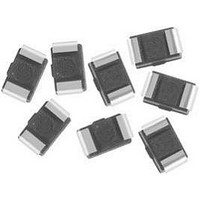
Wirewound, Surface Mount, Molded Inductors
INDUCTANCE VALUE
C
MIN.
10
10
10
10
10
10
10
10
10
10
10
10
10
10
10
10
10
10
10
10
10
10
10
10
20
20
20
20
20
20
20
Q
22 μH
H
(MHz)
MIN.
SRF
60.0
60.0
45.0
40.0
35.0
30.0
28.0
25.0
22.0
21.0
20.0
19.0
18.0
16.0
14.0
12.0
11.5
11.0
10.0
200
160
130
100
9.0
8.0
6.5
7.0
5.5
5.5
5.0
4.0
For technical questions, contact:
MAX.
DCR
0.11
0.12
0.15
0.16
0.18
0.20
0.22
0.24
1
()
0.3
0.3
0.4
0.4
0.5
0.6
0.7
0.8
0.9
1.2
1.4
1.6
1.9
2.2
2.6
3.5
4.0
4.5
6.5
7.5
11
13
9
INDUCTANCE TOLERANCE
RATED DC
8
CURRENT
(mA)
SIZE
1050
1000
950
900
850
800
750
700
650
650
600
600
550
500
450
400
370
330
300
280
260
240
220
200
180
160
140
120
120
100
90
± 10 %
(1)
1
2
FEATURES
• Molded construction provides superior strength
• Tape
• Compatible with vapor phase, infrared and
• Compliant to RoHS Directive 2002/95/EC
ELECTRICAL SPECIFICATIONS
Inductance Range: 1 μH to 330 μH
Inductance Tolerance: ± 10 %
Operating Temperature: - 40 °C to + 85 °C
Storage Temperature: - 40 °C to + 100 °C
TEST EQUIPMENT
• L & Q: H/P 4285A
• SRF: H/P 4286A
• DCR: H/P 34401
magnetics@vishay.com
DIMENSIONS in inches [millimeters]
PART MARKING
- Inductance value
and moisture resistance
handling, 500/reel, EIA-481
wave soldering methods
0.177 ± 0.012
0.055 ± 0.016
PACKAGE CODE
[4.5 ± 0.3]
[1.4 ± 0.4]
PACKAGE
E
CODE
A
D
and
ER
R
reel
A
packaging
0.126 ± 0.012
0.035 ± 0.008
2
JEDEC LEAD (Pb)-FREE STANDARD
[3.2 ± 0.3]
[0.9 ± 0.2]
E
INDUCTANCE
VALUE
B
E
2
for
IMCH-1812
0
automatic
e3
B
D
Vishay Dale
0.126 ± 0.012
www.vishay.com
[3.2 ± 0.3]
TOL.
C
K
1