CSTLS3M58G53-B0 Murata Electronics North America, CSTLS3M58G53-B0 Datasheet - Page 12
CSTLS3M58G53-B0
Manufacturer Part Number
CSTLS3M58G53-B0
Description
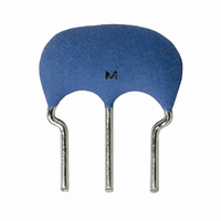
RESONATOR 3.58MHZ CERAMIC
Manufacturer
Murata Electronics North America
Series
CERALOCK®, CSTLSr
Type
Ceramicr
Specifications of CSTLS3M58G53-B0
Frequency
3.58MHz
Features
Built in Capacitor
Frequency Stability
±0.2%
Frequency Tolerance
±0.5%
Impedance
50 Ohm
Capacitance
15pF
Operating Temperature
-20°C ~ 80°C
Mounting Type
Through Hole
Package / Case
Radial - 3 Lead, 2.50mm Pitch
Size / Dimension
0.315" L x 0.118" W (8.00mm x 3.00mm)
Height
0.217" (5.50mm)
Lead Free Status / RoHS Status
Lead free / RoHS Compliant
Other names
490-1207
CSTS0358MG03
CSTS0358MG03
Available stocks
Company
Part Number
Manufacturer
Quantity
Price
Company:

Part Number:
CSTLS3M58G53-B0
Manufacturer:
MURATA
Quantity:
2 500


2
Note
• This PDF catalog is downloaded from the website of Murata Manufacturing co., ltd. Therefore, it’s specifications are subject to change or our products in it may be discontinued without advance notice. Please check with our
• This PDF catalog has only typical specifications because there is no space for detailed specifications. Therefore, please approve our product specifications or transact the approval sheet for product specifications before ordering.
sales representatives or product engineers before ordering.
10
2
(Note 1)
The relationship between the size of the resonator
and the resonant frequency is described as follows.
For example, the frequency doubles if the thickness
doubles, when thickness vibration is used.
The following relationship is obtained when the
length of the resonators is ℓ, the resonance
frequency is Fr, the speed of sound waves travelling
through piezoelectric ceramics, and the wavelength
is λ.
As seen in the above formula, the frequency
constant determines the size of the resonator.
Principles of CERALOCK
Notes
Fr . ℓ = Const.
(frequency constant, Fr . t for the thickness)
λ = 2 ℓ
C = Fr . λ = 2Fr . ℓ
(Min.Amplitude) (Max.Amplitude)
Fig. Ⅰ
Amplitude
Range of
Standing
Wave
®
(Note 2)
In Fig. 2-3, when resistance R
simplification, the impedance Z (ω) between two
terminals is expressed by the following formula.
Therefore from ω =2�F,
Fr = ωr/2� =
Fa = ωa/2� =
Z (ω) =
When ω =
When ω =
=
j ( ωL
1 +
jωC
jωC
1
1
2�
2�
0
0
C
L
C
C
1
1 –
1
( jωL
+ ( jωL
0
0
1
C
C
1
L
1
1
ωC
C
L
– ω
1
0
1
= ωr, Z (ωr) =0
C
L
1
1
C
1
1
Fig. Ⅱ
/(C
1
+
1
1
2
1
1
L
C
jωC
+
)
C
0+
0
1
1
/(C
jωC
0
C
L
C
1
1
1
1
1
)
0
1
+C
)
1
is omitted for
= ωa, Z (ωa) = ∞
)
1
)
= Fr
1+
C
C
1
0
P17E.pdf
10.8.3
Related parts for CSTLS3M58G53-B0
Image
Part Number
Description
Manufacturer
Datasheet
Request
R

Part Number:
Description:
BUZZER PIEZO 25VP-P SMD
Manufacturer:
Murata Electronics North America

Part Number:
Description:
CAP 4-ARRAY 680PF 100V X7R 1206
Manufacturer:
Murata Electronics North America
Datasheet:
Part Number:
Description:
CAP 4-ARRAY 1000PF 100V X7R 1206
Manufacturer:
Murata Electronics North America
Datasheet:
Part Number:
Description:
CAP 4-ARRAY 1800PF 100V X7R 1206
Manufacturer:
Murata Electronics North America
Datasheet:
Part Number:
Description:
CAP 4-ARRAY 68000PF 16V X7R 1206
Manufacturer:
Murata Electronics North America
Datasheet:

Part Number:
Description:
CAP CER 1000PF 50V 10% X7R 0402
Manufacturer:
Murata Electronics North America
Datasheet:
Part Number:
Description:
CAP CER 10000PF 16V 10% X7R 0402
Manufacturer:
Murata Electronics North America
Datasheet:

Part Number:
Description:
CAP 5.5-25PF 2.5X3.2MM SMD
Manufacturer:
Murata Electronics North America
Datasheet:

Part Number:
Description:
CAP 4.5-20PF 2.5X3.2MM SMD
Manufacturer:
Murata Electronics North America
Datasheet:

Part Number:
Description:
CAP 5.0-20PF 3.2X4.5MM SMD RED
Manufacturer:
Murata Electronics North America
Datasheet:

Part Number:
Description:
CAP 2.0-6.0PF 3.2X4.5MM SMD BLU
Manufacturer:
Murata Electronics North America
Datasheet:

Part Number:
Description:
CAP 1.4-3.0PF 3.2X4.5MM SMD BRN
Manufacturer:
Murata Electronics North America
Datasheet:

Part Number:
Description:
CAP 3.0-10PF 3.2X4.5MM SMD WHT
Manufacturer:
Murata Electronics North America
Datasheet:

Part Number:
Description:
CAP 2.0-6.0PF 4X4.5MM TOPADJ BLU
Manufacturer:
Murata Electronics North America
Datasheet:

Part Number:
Description:
CAP 8.5-40PF 4X4.5MM TOPADJ YEL
Manufacturer:
Murata Electronics North America
Datasheet: