RS605 Diodes Zetex, RS605 Datasheet

RECT SILICON 600V 6A RADIAL LEAD

RS605

Manufacturer Part Number
RS605
Description
RECT SILICON 600V 6A RADIAL LEAD
Manufacturer
Diodes Zetex
Datasheet

Specifications of RS605

Voltage - Peak Reverse (max)
600V
Current - Dc Forward (if)
6A
Diode Type
Single Phase
Speed
Standard Recovery >500ns, > 200mA (Io)
Mounting Type
Through Hole
Package / Case
RS-6
Phase Type
Single Phase
Number Of Elements
1
Peak Rep Rev Volt
600V
Rms Voltage (max)
420V
Peak Non-repetitive Surge Current (max)
250A
Avg. Forward Curr (max)
6@Ta=40CA
Rev Curr
10uA
Forward Voltage
1V
Package Type
RS-6
Operating Temp Range
-55C to 125C
Pin Count
4
Mounting
Through Hole
Operating Temperature Classification
Military
Lead Free Status / RoHS Status
Lead free by exemption / RoHS Compliant
Reverse Recovery Time (trr)
-
Lead Free Status / Rohs Status
Compliant

Available stocks

Company
Part Number
Manufacturer
Quantity
Price
Part Number:
RS605M
Manufacturer:
RECTRON
Quantity:
960
Features
Mechanical Data
Maximum Ratings and Electrical Characteristics
Single phase, 60Hz, resistive or inductive load.
For capacitive load, derate current by 20%.
Notes:
DS21314 Rev. 7 - 3
Maximum Recurrent Peak Reverse Voltage
Maximum RMS Bridge Input Voltage
Maximum DC Blocking Voltage
Maximum Average Forward Current
Peak Forward Surge current, 8.3 ms half sine-wave
superimposed on rated load
Maximum DC Forward Voltage Drop per element
at 3.0A
Maximum DC Reverse Current at Rated
DC Blocking Voltage, per element
Maximum Thermal Resistance (Note 1)
Operating Temperature Range
Storage Temperature Range
UL Recognized, File #94661
Ideal for Printed Circuit Board
Surge Overload Rating of 250A Peak
Low Forward Voltage Drop
The Plastic Material Carries UL Recognition 94V-0
Lead Free Finish, RoHS Compliant (Date Code 0514+)
(Note 2)
Case: RS-6, Molded Plastic
Terminals: Leads Solderable per MIL-STD-202, Method 208
Polarity: Symbols Marked on Body
Approx. Weight: 8.0 grams
2. EC Directive 2002/95/EC (RoHS) revision 13.2.2003. Glass and High Temperature Solder Exemptions Applied, see EU Directive Annex
1. Thermal Resistance junction to case per diode.
Notes 5 and 7.
Characteristic
@ T
@ T
@ T
@ T
A
A
A
C
= 25°C
= 40°C
= 100°C
= 100°C
www.diodes.com
Symbol
V
V
T
R
I
V
I
(AV)
FSM
V
RRM
RSM
T
STG
I
DC
R
F
JC
J
1 of 3
K
601
RS
L
J
50
35
50
H
-
@ T
602
100
100
~ ~
RS
70
A
B
A
= 25°C unless otherwise specified
+
C
603
200
140
200
RS
RS601 - RS607
G
D
-55 to +125
-55 to +150
E
6.0A BRIDGE RECTIFIER
250
6.0
1.0
1.0
4.7
604
400
280
400
10
RS
M
N
P
605
600
420
600
RS
Dim
All Dimensions in mm
G
M
A
B
C
D
E
H
K
L
N
P
J
606
800
560
800
RS
Diodes Incorporated
RS601-RS607
RS-6
22.7
10.3
25.4
16.8
Min
3.6
4.2
1.7
4.5
4.6
6.6
4.7
1.2
1000
1000
607
700
-
RS
Units
°C/W
Max
23.7
11.3
19.3
17.8
mA
4.1
4.7
2.2
6.8
5.6
7.1
5.2
1.3
V
V
V
A
A
V
C
C
A
-

Related parts for RS605

RS605 Summary of contents

Page 1

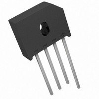
Features UL Recognized, File #94661 Ideal for Printed Circuit Board Surge Overload Rating of 250A Peak Low Forward Voltage Drop The Plastic Material Carries UL Recognition 94V-0 Lead Free Finish, RoHS Compliant (Date Code 0514+) (Note 2) Mechanical Data Case: ...

Page 2

AMBIENT TEMP Single Phase Half Wave 60 Hz Resistive or Inductive Load 100 T , JUNCTION TEMPERATURE (ºC) J Fig. 1 Forward Current Derating Curve 100ºC ...

Page 3

... Device RS601 RS602 RS603 RS604 RS605 RS606 RS607 Notes For packaging details, visit our website at http://www.diodes.com/datasheets/ap2008.pdf Diodes, Inc. and its subsidiaries reserve the right to make changes without further notice to any product herein to make corrections, modifications, enhance- ments, improvements, or other changes. Diodes, Inc. does not assume any liability arising out of the application or use of any product described herein; ...

Related keywords