KBU8G-E4/51 Vishay, KBU8G-E4/51 Datasheet - Page 2
KBU8G-E4/51
Manufacturer Part Number
KBU8G-E4/51
Description
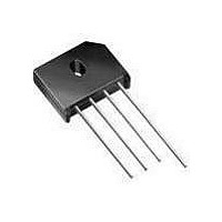
RECTIFIER BRIDGE 8A 400V KBU
Manufacturer
Vishay
Datasheet
1.KBU8B-E451.pdf
(4 pages)
Specifications of KBU8G-E4/51
Lead Free Status
Contains lead
Voltage - Peak Reverse (max)
400V
Current - Dc Forward (if)
6A
Diode Type
Single Phase
Speed
Standard Recovery >500ns, > 200mA (Io)
Mounting Type
Through Hole
Package / Case
4-SIP (KBU)
Product
Single Phase Bridge
Peak Reverse Voltage
400 V
Maximum Rms Reverse Voltage
280 V
Max Surge Current
300 A
Forward Voltage Drop
1 V
Maximum Reverse Leakage Current
10 uA
Maximum Operating Temperature
+ 150 C
Length
23.7 mm
Width
7.1 mm
Height
19.3 mm
Mounting Style
Through Hole
Minimum Operating Temperature
- 50 C
No. Of Phases
Single
Repetitive Reverse Voltage Vrrm Max
400V
Forward Current If(av)
8A
Forward Voltage Vf Max
1V
Diode Mounting Type
Through Hole
Operating Temperature Range
-55°C To +150°C
Lead Free Status / RoHS Status
Lead free / RoHS Compliant
Reverse Recovery Time (trr)
-
Lead Free Status / Rohs Status
Lead free / RoHS Compliant
Other names
KBU8G
KBU8G
KBU8G/1
KBU8G/1
KBU8G
KBU8G/1
KBU8G/1
Available stocks
Company
Part Number
Manufacturer
Quantity
Price


KBU8A thru KBU8M
Vishay General Semiconductor
Notes:
(1) Units mounted in free air, no heatsink, P.C.B. at 0.375" (9.5 mm) lead length with 0.5 x 0.5" (12 x 12 mm) copper pads
(2) Units mounted on a 3.0 x 3.0" x 0.11" thick (7.5 x 7.5 x 0.3 cm) aluminum plate heatsink
RATINGS AND CHARACTERISTICS CURVES
(T
www.vishay.com
2
ELECTRICAL CHARACTERISTICS (T
PARAMETER
Maximum instantaneous
forward drop per diode
Maximum DC reverse
current at rated DC blocking
voltage per diode
THERMAL CHARACTERISTICS (T
PARAMETER
Typical thermal resistance
ORDERING INFORMATION (Example)
PREFERRED P/N
KBU8J-E4/51
A
= 25 °C unless otherwise noted)
8
6
4
2
0
Figure 1. Derating Curve Output Rectified Current
0
P.C.B. Mounting, T
0.375" (9.5 mm) Lead Length
0.5 x 0.5" (12 x 12 mm) Copper Pads
60 Hz Resistive or Inductive Load
Heatsink Mounting,
T
Al. Plate (7.5 x 0.3 cm)
C
, 3.0 x 3.0 x 12" Thk.
50
Temperature (°C)
UNIT WEIGHT (g)
A
PDD-Americas@vishay.com, PDD-Asia@vishay.com, PDD-Europe@vishay.com
TEST CONDITIONS SYMBOL KBU8A KBU8B KBU8D KBU8G KBU8J KBU8K KBU8M
For technical questions within your region, please contact one of the following:
8.0 A
T
T
8.0
A
A
= 25 °C
= 125 °C
100
PREFERRED PACKAGE CODE
A
SYMBOL KBU8A KBU8B KBU8D KBU8G KBU8J KBU8K KBU8M
= 25 °C unless otherwise noted)
150
A
R
R
V
I
θJA
θJC
R
= 25 °C unless otherwise noted)
F
51
Figure 2. Maximum Non-Repetitive Peak Forward Surge Current
300
250
200
150
100
50
0
BASE QUANTITY
1
250
3.0
18
Number of Cycles at 60 Hz
1.0
1.0
10
(2)
(3)
1.0 Cycle
10
Anti-static PVC tray
DELIVERY MODE
Document Number: 88658
T
Single Sine-Wave
J
= 150 °C
Revision: 15-Apr-08
100
UNIT
UNIT
°C/W
mA
µA
V
Related parts for KBU8G-E4/51
Image
Part Number
Description
Manufacturer
Datasheet
Request
R


Part Number:
Description:
357-036-542-201 CARDEDGE 36POS DL .156 BLK LOPRO
Manufacturer:
Vishay
Datasheet:
Part Number:
Description:
357-036-542-201 CARDEDGE 36POS DL .156 BLK LOPRO
Manufacturer:
Vishay
Datasheet:
Part Number:
Description:
357-036-542-201 CARDEDGE 36POS DL .156 BLK LOPRO
Manufacturer:
Vishay
Datasheet:
Part Number:
Description:
357-036-542-201 CARDEDGE 36POS DL .156 BLK LOPRO
Manufacturer:
Vishay
Datasheet:
Part Number:
Description:
357-036-542-201 CARDEDGE 36POS DL .156 BLK LOPRO
Manufacturer:
Vishay
Datasheet:
Part Number:
Description:
357-036-542-201 CARDEDGE 36POS DL .156 BLK LOPRO
Manufacturer:
Vishay
Datasheet:
Part Number:
Description:
357-036-542-201 CARDEDGE 36POS DL .156 BLK LOPRO
Manufacturer:
Vishay
Datasheet:
Part Number:
Description:
357-036-542-201 CARDEDGE 36POS DL .156 BLK LOPRO
Manufacturer:
Vishay
Datasheet:
Part Number:
Description:
357-036-542-201 CARDEDGE 36POS DL .156 BLK LOPRO
Manufacturer:
Vishay
Datasheet:
Part Number:
Description:
357-036-542-201 CARDEDGE 36POS DL .156 BLK LOPRO
Manufacturer:
Vishay
Datasheet:
Part Number:
Description:
357-036-542-201 CARDEDGE 36POS DL .156 BLK LOPRO
Manufacturer:
Vishay
Datasheet:
Part Number:
Description:
357-036-542-201 CARDEDGE 36POS DL .156 BLK LOPRO
Manufacturer:
Vishay
Datasheet: