P11S1V0FLSY00102KL Vishay, P11S1V0FLSY00102KL Datasheet - Page 11
P11S1V0FLSY00102KL
Manufacturer Part Number
P11S1V0FLSY00102KL
Description
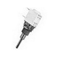
POTENTIOMETER, 1K POTENTIOMETER, 1K
Manufacturer
Vishay
Type
Potentiometerr
Series
P11r
Specifications of P11S1V0FLSY00102KL
Power Rating
1/2W
Resistance
1kohm
Tolerance (+ Or -)
10%
Number Of Turns
1Turn
Technology
Cermet
Mounting Style
Panel
Termination Style
Solder Lug
Operating Temp Range
-55C to 125C
Failure Rate
Not Required
Shaft Diameter (mm)
6mm
Product Diameter (mm)
Not Requiredmm
Product Height (mm)
13.1mm
Product Depth (mm)
12.5mm
Temperature Coefficient
±150
Resistors Element Type
VARIABLE ROTARY CERMET
Resistance, Track
1KR
Case Style
PANEL MOUNT
Temp, Op. Max
125(DEGREE C)
Temp, Op. Min
-55(DEGREE C)
Temp. Coeff,
ROHS COMPLIANT
Lead Free Status / RoHS Status
Compliant


P11S, P11A
Vishay Sfernice
www.vishay.com
11
P11 OPTION: PUSH/PUSH OR MOMENTARY/PUSH SWITCH MODULES
MODULES: PUSH/PUSH SWITCH RSPP
MOMENTARY/PUSH SWITCH RSMP
They have to be the last element of potentiometer
Options:
2 reversing switches F2
6 reversing switches F6
Not available with panel sealed option.
Number of modules before the switch limited to 3 modules.
Length of shaft (FMF) 25 mm maximum.
RSPP F2: PUSH/PUSH SWITCH WITH TWO REVERSING
SWITCHES
Idle position: The contact is made between 1 and 2 and a and b.
It is open between 2 and 3 and b and c.
Pushed position: The contact is made between 2 and 3
and b and c. It is open between 1 and 2 and a and b.
ORDERING INFORMATION (First order only for special code creation)
RSPP: Push/push
RSMP: Momentary/push
(0.013)
(0.051)
3.3
1.3
RSPP
See also Application Note:
Cermet (P11S) or Conductive Plastic Elements (P11A)
4 reversing switches F4
8 reversing switches F8
(1.10)
40.8 (1.60)
28
(0.15)
For technical questions, contact:
12.5 mm Modular Panel Potentiometer
1 2 3
a b c
4
4
(0.15)
www.vishay.com/doc?51001
3.6 (0.14)
sfer@vishay.com
ELECTRICAL DIAGRAM
• Push/push or momentary push
• Current up to 2 A
• Sealing IP60
SWITCH SPECIFICATIONS
Switching Power Maximum
Switching Current Maximum
Maximum Current Through Element
Contact Resistance
Dielectric
Strength
Maximum Voltage Operation
Insulation Resistance Between Contacts
Life at P
Minimal Travel
Operating Temperature
F2: 2 reversing switches (standard version)
F4: 4 reversing switches
F6: 6 reversing switches
F8: 8 reversing switches
and
www.vishay.com/doc?52029
max.
IDLE POSITION
F2
Terminal to Terminal
Terminal to Bushing
a
1
b
2
RSPP F2
PUSHED POSITION
c
3
Document Number: 51031
100 000 actuations
3.3 mm to 4.7 mm
- 40 °C to + 70 °C
Revision: 21-Feb-11
1500 V
2000 V
50 VA
100 m
10
250 V
0.5 A
2 A
3
M
RMS
RMS
Related parts for P11S1V0FLSY00102KL
Image
Part Number
Description
Manufacturer
Datasheet
Request
R

Part Number:
Description:
357-036-542-201 CARDEDGE 36POS DL .156 BLK LOPRO
Manufacturer:
Vishay
Datasheet:
Part Number:
Description:
357-036-542-201 CARDEDGE 36POS DL .156 BLK LOPRO
Manufacturer:
Vishay
Datasheet:
Part Number:
Description:
357-036-542-201 CARDEDGE 36POS DL .156 BLK LOPRO
Manufacturer:
Vishay
Datasheet:
Part Number:
Description:
357-036-542-201 CARDEDGE 36POS DL .156 BLK LOPRO
Manufacturer:
Vishay
Datasheet:
Part Number:
Description:
357-036-542-201 CARDEDGE 36POS DL .156 BLK LOPRO
Manufacturer:
Vishay
Datasheet:
Part Number:
Description:
357-036-542-201 CARDEDGE 36POS DL .156 BLK LOPRO
Manufacturer:
Vishay
Datasheet:
Part Number:
Description:
357-036-542-201 CARDEDGE 36POS DL .156 BLK LOPRO
Manufacturer:
Vishay
Datasheet:
Part Number:
Description:
357-036-542-201 CARDEDGE 36POS DL .156 BLK LOPRO
Manufacturer:
Vishay
Datasheet:
Part Number:
Description:
357-036-542-201 CARDEDGE 36POS DL .156 BLK LOPRO
Manufacturer:
Vishay
Datasheet:
Part Number:
Description:
357-036-542-201 CARDEDGE 36POS DL .156 BLK LOPRO
Manufacturer:
Vishay
Datasheet:
Part Number:
Description:
357-036-542-201 CARDEDGE 36POS DL .156 BLK LOPRO
Manufacturer:
Vishay
Datasheet:
Part Number:
Description:
357-036-542-201 CARDEDGE 36POS DL .156 BLK LOPRO
Manufacturer:
Vishay
Datasheet:
Part Number:
Description:
357-036-542-201 CARDEDGE 36POS DL .156 BLK LOPRO
Manufacturer:
Vishay
Datasheet:
Part Number:
Description:
357-036-542-201 CARDEDGE 36POS DL .156 BLK LOPRO
Manufacturer:
Vishay
Datasheet:
Part Number:
Description:
357-036-542-201 CARDEDGE 36POS DL .156 BLK LOPRO
Manufacturer:
Vishay
Datasheet: