ATAVRSBIN1 Atmel, ATAVRSBIN1 Datasheet - Page 3
ATAVRSBIN1
Manufacturer Part Number
ATAVRSBIN1
Description
Acceleration Sensor Development Tools 9DOF Inertial Sensor Board 1
Manufacturer
Atmel
Datasheet
1.ATAVRSBIN1.pdf
(7 pages)
Specifications of ATAVRSBIN1
Sensing Axis
Triple Axis
Output Type
Digital
Interface Type
I2C
Operating Voltage
3.3 V
For Use With/related Products
AVR Xplain
Lead Free Status / RoHS Status
Lead free / RoHS Compliant
Available stocks
Company
Part Number
Manufacturer
Quantity
Price
Company:

Part Number:
ATAVRSBIN1
Manufacturer:
Atmel
Quantity:
135


AVR4200
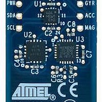
4 Hardware layout
Figure 4-1
shows the physical arrangement of the Inertial One Sensors Xplained
development board.
NOTE
All three sensors have their X, Y, and Z axes aligned, and a symbol is provided to
indicate their directional alignment.
Figure 4-1. Sensor arrangement.
The Inertial One Sensors Xplained development board must be attached to the
correct headers on the Xplain MCU board to ensure proper operation. All the Sensors
Xplained development boards attach to headers J1 and J2 on the MCU boards, and a
board alignment indicator is printed on the board to provide to aid correct alignment.
As an example,
Figure 4-2
shows the orientation of the Pressure One Sensors
Xplained development board when attached to the UC3-L0 Xplained MCU board.
Figure 4-2. Correct board attachment orientation.
3
8354A-AVR-11/10
Related parts for ATAVRSBIN1
Image
Part Number
Description
Manufacturer
Datasheet
Request
R

Part Number:
Description:
DEV KIT FOR AVR/AVR32
Manufacturer:
Atmel
Datasheet:

Part Number:
Description:
INTERVAL AND WIPE/WASH WIPER CONTROL IC WITH DELAY
Manufacturer:
ATMEL Corporation
Datasheet:
Part Number:
Description:
Low-Voltage Voice-Switched IC for Hands-Free Operation
Manufacturer:
ATMEL Corporation
Datasheet:
Part Number:
Description:
MONOLITHIC INTEGRATED FEATUREPHONE CIRCUIT
Manufacturer:
ATMEL Corporation
Datasheet:
Part Number:
Description:
AM-FM Receiver IC U4255BM-M
Manufacturer:
ATMEL Corporation
Datasheet:
Part Number:
Description:
Monolithic Integrated Feature Phone Circuit
Manufacturer:
ATMEL Corporation
Datasheet:
Part Number:
Description:
Multistandard Video-IF and Quasi Parallel Sound Processing
Manufacturer:
ATMEL Corporation
Datasheet:
Part Number:
Description:
High-performance EE PLD
Manufacturer:
ATMEL Corporation
Datasheet:
Part Number:
Description:
8-bit Flash Microcontroller
Manufacturer:
ATMEL Corporation
Datasheet:
Part Number:
Description:
2-Wire Serial EEPROM
Manufacturer:
ATMEL Corporation
Datasheet: