KBPC601PBF Vishay, KBPC601PBF Datasheet - Page 2
KBPC601PBF
Manufacturer Part Number
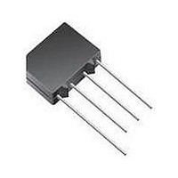
KBPC601PBF
Description
Bridge Rectifiers 100 Volt 6.0 Amp
Manufacturer
Vishay
Datasheet
1.KBPC602PBF.pdf
(4 pages)
Specifications of KBPC601PBF
Product
Single Phase Bridge
Peak Reverse Voltage
100 V
Max Surge Current
137 A
Forward Voltage Drop
1.2 V
Maximum Reverse Leakage Current
10 uA
Maximum Operating Temperature
+ 150 C
Length
15.75 mm
Width
15.75 mm
Height
5.33 mm
Mounting Style
Through Hole
Minimum Operating Temperature
- 40 C
Package / Case
D-72
No. Of Phases
Single
Repetitive Reverse Voltage Vrrm Max
100V
Forward Current If(av)
6A
Forward Voltage Vf Max
1.2V
Diode Mounting Type
Through Hole
Lead Free Status / RoHS Status
Lead free / RoHS Compliant


KBPC1, KBPC6 Series
Vishay High Power Products
www.vishay.com
2
FORWARD CONDUCTION
PARAMETER
Maximum DC output current
Maximum peak one cycle,
non-repetitive surge current
Maximum I
Maximum I
Maximum peak forward voltage per diode
Typical peak reverse leakage per diode
Operating frequency range
Maximum repetitive peak reverse
voltage range
THERMAL AND MECHANICAL SPECIFICATIONS
PARAMETER
Operating and storage temperature range
Thermal resistance, junction to case
Approximate weight
93585_01
4.0
3.5
3.0
2.5
2.0
1.5
1.0
0.5
0.0
2
2
t capability for fusing
√t capability for fusing
Maximum Allowable Case Temperature (°C)
0
KBPC1...
20
Fig. 1 - Case Temperature Ratings
Capacitive load
40
60
Resistive, inductive load
80
For technical questions, contact:
100
SYMBOL
120
V
I
V
I
I
FSM
I
2
RRM
I
RM
2
FM
O
f
√t
t
140
Single Phase Rectifier
SYMBOL
160
Bridge, 3 A, 6 A
T
T
T
t = 10 ms, 20 ms
t = 8.3 ms, 16.7 ms
t = 10 ms
t = 8.3 ms
t = 10 ms
t = 8.3 ms
t = 0.1 ms to 10 ms, no voltage reapplied
I
T
T
R
FM
J
C
C
J
J
, T
thJC
= 25 °C, 100 % V
= 150 °C, 100 % V
= 50 °C, resistive or inductive load
= 50 °C, capacitive load
= 0.5 x I
Stg
O
TEST CONDITIONS
, T
indmodules@vishay.com
J
= 25 °C
RRM
RRM
Following any rated load
condition and with rated
V
Initial T
100 % V
KBPC1
93585_02
RRM
0.18
5
-
reapplied
8
7
6
5
4
3
2
1
0
J
RRM
Maximum Allowable Case Temperature (°C)
= T
0
- 40 to 150
KBPC6...
J
reapplied
maximum
20
Fig. 2 - Case Temperature Ratings
Capacitive load
40
KBPC6
0.21
60
6
-
KBPC1
12.5
11.4
17.7
16.1
Resistive, inductive load
177
3.0
2.4
1.1
1.0
80
50
55
10
40 to 1000
50 to 1000
Document Number: 93585
100
Revision: 23-Dec-08
KBPC6
120
1000
1105
125
137
110
6.0
4.7
1.2
1.0
78
71
10
UNITS
140
K/W
oz.
°C
g
160
UNITS
A
A
mA
Hz
2
A
V
V
2
√s
s
Related parts for KBPC601PBF
Image
Part Number
Description
Manufacturer
Datasheet
Request
R

Part Number:
Description:
Bridge Rectifiers 100 Volt 6.0 Amp
Manufacturer:
Vishay
Datasheet:

Part Number:
Description:
High Current Bridge Rectifier
Manufacturer:
Comchip Technology
Datasheet:

Part Number:
Description:
SINGLE PHASE15/25/35/50 AMPS. SILICON BRIDGE RECTIFIERS
Manufacturer:
YANGJIE [Yangzhou yangjie electronic co., ltd]
Datasheet:
Part Number:
Description:
SILICON BRIDGE RECTIFIERS
Manufacturer:
GOOD-ARK [GOOD-ARK Electronics]
Datasheet:

Part Number:
Description:
KBPC-W/25A/400V/Gen.Purp. Bridge Rect./Metal case/SP
Manufacturer:
Pan Jit International Inc.
Part Number:
Description:
KBPC/25A/800V/Gen.Purp. Bridge Rect./Metal case/SP
Manufacturer:
Pan Jit International Inc.
Part Number:
Description:
KBPC/35A/600V/Gen.Purp. Bridge Rect./Metal case/SP
Manufacturer:
Pan Jit International Inc.
Part Number:
Description:
KBPC/35A/1000V/Gen.Purp. Bridge Rect./Metal case/SP
Manufacturer:
Pan Jit International Inc.
Part Number:
Description:
KBPC-W/35A/1000V/Gen.Purp. Bridge Rect./Metal case/SP
Manufacturer:
Pan Jit International Inc.
Part Number:
Description:
KBPC/50A/1000V/Gen.Purp. Bridge Rect./Metal case/SP
Manufacturer:
Pan Jit International Inc.

Part Number:
Description:
KBPC, VRRM 1000, VRMS 700, VDC 1000, IF(AV) 25.00, IFSM 300, VF 1.10
Manufacturer:
HVCA
Part Number:
Description:
KBPC-8/10, VRRM 600, VRMS 420, VDC 600, IF(AV) 10.00, IFSM 250, VF 1.10
Manufacturer:
HVCA
Part Number:
Description:
KBPC-8/10, VRRM 200, VRMS 140, VDC 200, IF(AV) 10.00, IFSM 250, VF 1.10
Manufacturer:
HVCA
Part Number:
Description:
KBPC, VRRM 800, VRMS 560, VDC 800, IF(AV) 15.00, IFSM 200, VF 1.10
Manufacturer:
HVCA
Part Number:
Description:
KBPC-8/10, VRRM 100, VRMS 70, VDC 100, IF(AV) 10.00, IFSM 250, VF 1.10
Manufacturer:
HVCA
Datasheet: