110MT140KPBF Vishay, 110MT140KPBF Datasheet - Page 5
110MT140KPBF
Manufacturer Part Number
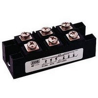
110MT140KPBF
Description
Bridge Rectifiers 1400 Volt 110 Amp
Manufacturer
Vishay
Specifications of 110MT140KPBF
Package / Case
INT-A-PAK
Product
Three Phase Bridge
Peak Reverse Voltage
1400 V
Max Surge Current
1000 A
Forward Voltage Drop
1.4 V
Maximum Reverse Leakage Current
10000 uA
Maximum Operating Temperature
+ 150 C
Length
94 mm
Width
35 mm
Height
30 mm
Mounting Style
Screw
Minimum Operating Temperature
- 40 C
Repetitive Reverse Voltage Vrrm Max
1.4kV
Leaded Process Compatible
Yes
Lead Free Status / RoHS Status
Lead free / RoHS Compliant


www.irf.com
700
650
600
550
500
450
400
350
300
250
200
150
140
130
120
110
100
90
80
70
60
50
Number Of Equal Amplitude Half Cycle Current Pulses (N)
Fig. 4 - Maximum Non-Repetitive Surge Current
1
0
Fig. 6 - Current Ratings Characteristics
90MT..KB Series
400
350
300
250
200
150
100
At Any Rated Load Condition And With
Rated V
20
50
0
0
40
Total Output Current (A)
90MT..KB Series
T = 150°C
J
RRM
20
60
Applied Following Surge.
Total Output Current (A)
10
80
40
110MT..KB Series
@ 60 Hz 0.0083 s
@ 50 Hz 0.0100 s
100 120 140 160
Initial T = 150°C
(Rect)
120°
(Rect)
60
120°
Fig. 3 - Total Power Loss Characteristics
J
80
100
100
120
0
Maximum Allowable Ambient Temperature (°C)
25
1000
50
800
750
700
650
600
550
500
450
400
350
300
250
200
150
100
10
Fig. 5 - Maximum Non-Repetitive Surge Current
1
0.01
Fig. 7 - Forward Voltage Drop Characteristics
0
75
Maximum Non Repetitive Surge Current
90MT..KB Series
Instantaneous Forward Voltage (V)
100
1
Bulletin I27501 rev. A 05/03
90-110MT..KB Series
Pulse Train Duration (s)
Versus Pulse Train Duration.
125
2
Rated V
0.1
No Voltage Reapplied
110MT..KB Series
Per Junction
150
T = 25°C
T = 150°C
J
J
3
Initial T = 150°C
RRM
Reapplied
J
4
5
1
5
Related parts for 110MT140KPBF
Image
Part Number
Description
Manufacturer
Datasheet
Request
R

Part Number:
Description:
357-036-542-201 CARDEDGE 36POS DL .156 BLK LOPRO
Manufacturer:
Vishay
Datasheet:
Part Number:
Description:
357-036-542-201 CARDEDGE 36POS DL .156 BLK LOPRO
Manufacturer:
Vishay
Datasheet:
Part Number:
Description:
357-036-542-201 CARDEDGE 36POS DL .156 BLK LOPRO
Manufacturer:
Vishay
Datasheet:
Part Number:
Description:
357-036-542-201 CARDEDGE 36POS DL .156 BLK LOPRO
Manufacturer:
Vishay
Datasheet:
Part Number:
Description:
357-036-542-201 CARDEDGE 36POS DL .156 BLK LOPRO
Manufacturer:
Vishay
Datasheet:
Part Number:
Description:
357-036-542-201 CARDEDGE 36POS DL .156 BLK LOPRO
Manufacturer:
Vishay
Datasheet:
Part Number:
Description:
357-036-542-201 CARDEDGE 36POS DL .156 BLK LOPRO
Manufacturer:
Vishay
Datasheet:
Part Number:
Description:
357-036-542-201 CARDEDGE 36POS DL .156 BLK LOPRO
Manufacturer:
Vishay
Datasheet:
Part Number:
Description:
357-036-542-201 CARDEDGE 36POS DL .156 BLK LOPRO
Manufacturer:
Vishay
Datasheet:
Part Number:
Description:
357-036-542-201 CARDEDGE 36POS DL .156 BLK LOPRO
Manufacturer:
Vishay
Datasheet:
Part Number:
Description:
357-036-542-201 CARDEDGE 36POS DL .156 BLK LOPRO
Manufacturer:
Vishay
Datasheet:
Part Number:
Description:
357-036-542-201 CARDEDGE 36POS DL .156 BLK LOPRO
Manufacturer:
Vishay
Datasheet:
Part Number:
Description:
357-036-542-201 CARDEDGE 36POS DL .156 BLK LOPRO
Manufacturer:
Vishay
Datasheet:
Part Number:
Description:
357-036-542-201 CARDEDGE 36POS DL .156 BLK LOPRO
Manufacturer:
Vishay
Datasheet:
Part Number:
Description:
357-036-542-201 CARDEDGE 36POS DL .156 BLK LOPRO
Manufacturer:
Vishay
Datasheet: