BZB984-C7V5,115 NXP Semiconductors, BZB984-C7V5,115 Datasheet - Page 5
BZB984-C7V5,115
Manufacturer Part Number
BZB984-C7V5,115
Description
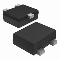
DIODE ZENER DUAL 7.5V SOT663
Manufacturer
NXP Semiconductors
Datasheet
1.BZB984-C10115.pdf
(9 pages)
Specifications of BZB984-C7V5,115
Package / Case
SOT-663
Voltage - Zener (nom) (vz)
7.5V
Voltage - Forward (vf) (max) @ If
900mV @ 10mA
Current - Reverse Leakage @ Vr
1µA @ 5V
Configuration
1 Pair Common Anode
Power - Max
265mW
Impedance (max) (zzt)
6 Ohm
Tolerance
±5%
Mounting Type
Surface Mount
Zener Voltage
7.45 V
Voltage Tolerance
5 %
Voltage Temperature Coefficient
3.6 mV / K
Power Dissipation
425 mW
Maximum Reverse Leakage Current
1 uA
Maximum Zener Impedance
15 Ohms
Maximum Operating Temperature
+ 150 C
Mounting Style
SMD/SMT
Minimum Operating Temperature
- 65 C
Lead Free Status / RoHS Status
Lead free / RoHS Compliant
Other names
934057238115
BZB984-C7V5 T/R
BZB984-C7V5 T/R
BZB984-C7V5 T/R
BZB984-C7V5 T/R


NXP Semiconductors
THERMAL CHARACTERISTICS
Notes
1. Solder points on cathode tabs.
2. Device mounted on an FR4 printed-circuit board.
Soldering
The only recommended soldering method is reflow soldering.
GRAPHICAL DATA
2002 Jun 21
handbook, halfpage
R
R
SYMBOL
Voltage regulator double diodes
th j-s
th j-a
T
Fig.2
j
(mA)
= 25 °C.
300
I F
200
100
0
0.6
Forward current as a function of forward
voltage; typical values.
thermal resistance from junction to soldering point
thermal resistance from junction to ambient
0.7
0.8
PARAMETER
0.9
V F (V)
MLD362
1
5
handbook, halfpage
BZB984-C2V4 to C4V7.
T
Fig.3
(mV/K)
2 diodes loaded; note 1
1 diode loaded; note 1
2 diodes loaded; note 2
1 diode loaded; note 2
j
= 25 to 150 °C.
S Z
−0.5
−1.5
0.5
−1
−2
0
10
−1
CONDITIONS
Temperature coefficient as a function of
working current; typical values.
2V4
1
2V7
BZB984 series
10
VALUE
125
230
294
472
Product data sheet
I Z (mA)
4V7
4V3
3V9
3V6
MLD363
3V3
3V0
10
UNIT
2
K/W
K/W
K/W
K/W
Related parts for BZB984-C7V5,115
Image
Part Number
Description
Manufacturer
Datasheet
Request
R

Part Number:
Description:
DIODE ZENER DUAL 12V SOT663
Manufacturer:
NXP Semiconductors
Datasheet:
Part Number:
Description:
DIODE ZENER DUAL 15V SOT663
Manufacturer:
NXP Semiconductors
Datasheet:
Part Number:
Description:
DIODE ZENER DUAL 2.4V SOT663
Manufacturer:
NXP Semiconductors
Datasheet:
Part Number:
Description:
DIODE ZENER DUAL 2.7V SOT663
Manufacturer:
NXP Semiconductors
Datasheet:
Part Number:
Description:
DIODE ZENER DUAL 3.3V SOT663
Manufacturer:
NXP Semiconductors
Datasheet:
Part Number:
Description:
DIODE ZENER DUAL 4.7V SOT663
Manufacturer:
NXP Semiconductors
Datasheet:
Part Number:
Description:
DIODE ZENER DUAL 5.1V SOT663
Manufacturer:
NXP Semiconductors
Datasheet:
Part Number:
Description:
DIODE ZENER DUAL 5.6V SOT663
Manufacturer:
NXP Semiconductors
Datasheet:
Part Number:
Description:
DIODE ZENER DUAL 6.2V SOT663
Manufacturer:
NXP Semiconductors
Datasheet:

Part Number:
Description:
Zener Diodes DIODE ZENER 5 PCT TAPE-7
Manufacturer:
NXP Semiconductors
Datasheet:
Part Number:
Description:
Zener Diodes DIODE ZENER 5 PCT TAPE-7
Manufacturer:
NXP Semiconductors
Datasheet:
Part Number:
Description:
Zener Diodes DIODE ZENER 5 PCT TAPE-7
Manufacturer:
NXP Semiconductors
Datasheet:
Part Number:
Description:
Zener Diodes DIODE ZENER 5 PCT TAPE-7
Manufacturer:
NXP Semiconductors
Datasheet:
Part Number:
Description:
Zener Diodes DIODE ZENER 5 PCT TAPE-7
Manufacturer:
NXP Semiconductors
Datasheet:
Part Number:
Description:
Zener Diodes DIODE ZENER 5 PCT TAPE-7
Manufacturer:
NXP Semiconductors
Datasheet: