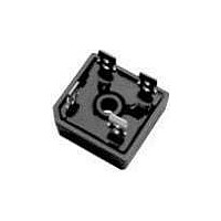
GBPC2502/1 Vishay, GBPC2502/1 Datasheet - Page 3

GBPC2502/1
Manufacturer Part Number
GBPC2502/1
Description
Bridge Rectifiers 25 Amp 200 Volt
Manufacturer
Vishay
Specifications of GBPC2502/1
Package / Case
GBPC
Product
Single Phase Bridge
Peak Reverse Voltage
200 V
Maximum Rms Reverse Voltage
140 V
Forward Continuous Current
25 A
Max Surge Current
300 A
Forward Voltage Drop
1.1 V
Maximum Reverse Leakage Current
5 uA
Maximum Operating Temperature
+ 150 C
Length
28.8 mm
Width
28.8 mm
Height
7.62 mm
Mounting Style
Through Hole
Minimum Operating Temperature
- 55 C
Diode Type
Bridge Rectifier
Peak Reflow Compatible (260 C)
No
Current Rating
25A
Leaded Process Compatible
No
Forward Voltage
1.1V
Forward Current If
12.5A
Phase Type
Single Phase
Number Of Elements
1
Peak Rep Rev Volt
200V
Rms Voltage (max)
140V
Peak Non-repetitive Surge Current (max)
300A
Avg. Forward Curr (max)
25A
Rev Curr
5uA
Package Type
Case GBPC
Operating Temp Range
-55C to 150C
Pin Count
4
Mounting
Screw
Operating Temperature Classification
Military
Lead Free Status / RoHS Status
Lead free / RoHS Compliant
Lead Free Status / RoHS Status
Contains lead / RoHS non-compliant, Lead free / RoHS Compliant
RATINGS AND CHARACTERISTICS CURVES
(T
Document Number: 88612
Revision: 15-Apr-08
A
= 25 °C unless otherwise noted)
40
35
30
25
20
15
10
80
70
60
50
40
30
20
10
40
35
30
25
20
15
10
5
0
5
0
0
0
0
0
Figure 1. Maximum Output Rectified Current
Figure 2. Maximum Output Rectified Current
GBPC35
R
GBPC25
R
GBPC15
R
GBPC12
R
60 Hz
Resistive or
Inductive Load
thSA
thSA
thSA
thSA
10
T
Figure 3. Maximum Power Dissipation
25
J
Capacitive Load
= 0.5 °C/W
= 0.5 °C/W
= 1.0 °C/W
= 1.0 °C/W
= T
20
J
Max.
50
Average Output Current (A)
10
Ambient Temperature (°C)
30
Case Temperature (°C)
75
40
Bridges Mounted on
9.5 x 3.5 x 4.6"
(22.9 x 8.9 x 11.7 cm)
AL, Finned Plate
PDD-Americas@vishay.com, PDD-Asia@vishay.com, PDD-Europe@vishay.com
100
50
For technical questions within your region, please contact one of the following:
20
5 x 6 x 4.9"
AL, Finned Plate
5 x 4 x 3"
AL, Finned Plate
60
125
Resistive or
Inductive Load
70
6 x 2.2 x 2.2"
AL, Finned Plate
60 Hz
Resistive or
Inductive Load
150
30
80
175
90
100
200
40
GBPC12, GBPC15, GBPC25 & GBPC35
Figure 5. Typical Instantaneous Forward Characteristics Per Diode
Figure 6. Typical Reverse Leakage Characteristics Per Diode
Figure 4. Maximum Non-Repetitive Peak Forward Surge
1000
1000
100
100
100
0.1
0.1
10
10
10
1
1
0.4
1
0
Vishay General Semiconductor
Percent of Rated Peak Reverse Voltage (%)
T
10
A
0.5
= 100 °C
Instantaneous Forward Voltage (V)
20
T
Number of Cycles at 60 Hz
A
0.6
= 125 °C
30
Current Per Diode
1.0 Cycle
T
40
A
0.7
= 150 °C
T
T
T
T
A
A
A
A
10
50
= 125 °C
= 150 °C
= 100 °C
= 25 °C
T
0.5 ms Single Sine-Wave
0.8
J
= T
60
GBPC12
J
Max.
70
0.9
GBPC35
T
A
80
= 25 °C
GBPC15
GBPC25
1.0
90
www.vishay.com
100
100
1.1
3


