P11A2C0BJSZ00103MA Vishay, P11A2C0BJSZ00103MA Datasheet - Page 3
P11A2C0BJSZ00103MA
Manufacturer Part Number
P11A2C0BJSZ00103MA
Description
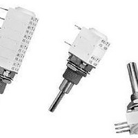
TRIMMERS & POTENTIOMETERS SFERNICE / P11A 2 C 0 BJ S Z00 10K 20% A E3
Manufacturer
Vishay
Series
P11r
Datasheet
1.P11S1A0BGSY00101KA.pdf
(15 pages)
Specifications of P11A2C0BJSZ00103MA
Resistance
10 KOhms
Tolerance
20 %
Power Rating
0.5 Watt (1/2 Watt)
Termination Style
Pins
Number Of Turns
1
Element Type
Conductive Plastic
Shaft Type
Slotted
Operating Temperature Range
- 55 C to + 125 C
Lead Free Status / Rohs Status
Lead free / RoHS Compliant


P11S, P11A
Vishay Sfernice
www.vishay.com
3
MECHANICAL (initial)
Mechanical Travel
Operating Torque (Typical)
End Stop Torque (All Bushing Except G)
End Stop Torque for Bushing G
Tightening Torque
Weight
ENVIRONMENTAL
Operating Temperature Range
Climatic Category
Sealing
MARKING
Potentiometer Module
Switch Module
Indent Module
PERFORMANCES
TESTS
Electrical Endurance
Change of Temperature
Damp Heat, Steady State
Mechanical Endurance
Climatic Sequence
Shock
Vibration
Vishay logo, nominal ohmic value (, k, M), two stars
identify P11A version, tolerance in % - variation law,
manufacturing date (four digits), “3” for the lead 3
Version, manufacturing date (four digits), “c” for common lead
Version, manufacturing date (four digits)
See also Application Note:
Three to Seven Modules (Per Module)
Cermet (P11S) or Conductive Plastic Elements (P11A)
6 mm, 7 mm, and 1/4" Dia. Bushings
cold - 55 °C/damp heat, 5 cycles
Dry heat at + 125 °C/damp heat
3 mm, 4 mm, and 1/8" Dia. Shafts
+ 40 °C, 93 % relative humidity
P11S: 56 days, P11A: 21 days
90’/30’ - ambient temp. 70 °C
- 55 °C to + 125 °C, 5 cycles
10 mm and 3/8" Dia. Bushings
3 shocks - 3 directions
0.75 mm or 10 g’s, 6 h
1000 h at rated power
Single and Dual Assemblies
For technical questions, contact:
12.5 mm Modular Panel Potentiometer
6 mm and 1/4" Dia. Shafts
10 Hz to 55 Hz
CONDITIONS
50 000 cycles
50 g’s, 11 ms
www.vishay.com/doc?51001
All Shafts Dia.
Contact resistance variation
Contact resistance variation
Insulation resistance
sfer@vishay.com
0.4 Ncm to 1.8 Ncm max. (0.57 oz.-inch to 2.55 oz.-inch max.)
0.2 Ncm to 0.3 Ncm max. (0.28 oz.-inch to 0.42 oz.-inch max.)
PACKAGING
Box
R
V
and
R
R
R
R
R
R
R
- 55 °C to + 125 °C
1-2
1-2
T
T
T
T
T
T
T
/R
/R
/R
/R
/R
/R
/R
/R
/V
www.vishay.com/doc?52029
55/125/21
T
T
T
T
T
T
T
1-3
1-2
7 g to 9 g per module (0.25 oz. to 0.32 oz.)
P11A
IP64
TYPICAL VALUE AND DRIFTS
150 Ncm max. (13 lb-inch max.)
250 Ncm max. (21 lb-inch max.)
25 Ncm max. (2.1 lb-inch max.)
80 Ncm max. (6.8 lb-inch max.)
40 Ncm max. (3.4 lb-inch max.)
300° ± 5°
> 1000 M
± 0.2 %
± 0.2 %
± 0.5 %
± 0.2 %
± 0.5 %
± 2 %
± 4 %
± 2 %
± 5 %
± 5 %
± 1 %
P11S
- 55 °C to + 125 °C
Document Number: 51031
55/125/56
P11S
Revision: 21-Feb-11
IP64
> 10 M
± 0.5 %
± 0.2 %
± 0.5 %
± 0.2 %
± 0.5 %
± 10 %
P11A
± 5 %
± 5 %
± 6 %
± 4 %
-
Related parts for P11A2C0BJSZ00103MA
Image
Part Number
Description
Manufacturer
Datasheet
Request
R

Part Number:
Description:
357-036-542-201 CARDEDGE 36POS DL .156 BLK LOPRO
Manufacturer:
Vishay
Datasheet:
Part Number:
Description:
357-036-542-201 CARDEDGE 36POS DL .156 BLK LOPRO
Manufacturer:
Vishay
Datasheet:
Part Number:
Description:
357-036-542-201 CARDEDGE 36POS DL .156 BLK LOPRO
Manufacturer:
Vishay
Datasheet:
Part Number:
Description:
357-036-542-201 CARDEDGE 36POS DL .156 BLK LOPRO
Manufacturer:
Vishay
Datasheet:
Part Number:
Description:
357-036-542-201 CARDEDGE 36POS DL .156 BLK LOPRO
Manufacturer:
Vishay
Datasheet:
Part Number:
Description:
357-036-542-201 CARDEDGE 36POS DL .156 BLK LOPRO
Manufacturer:
Vishay
Datasheet:
Part Number:
Description:
357-036-542-201 CARDEDGE 36POS DL .156 BLK LOPRO
Manufacturer:
Vishay
Datasheet:
Part Number:
Description:
357-036-542-201 CARDEDGE 36POS DL .156 BLK LOPRO
Manufacturer:
Vishay
Datasheet:
Part Number:
Description:
357-036-542-201 CARDEDGE 36POS DL .156 BLK LOPRO
Manufacturer:
Vishay
Datasheet:
Part Number:
Description:
357-036-542-201 CARDEDGE 36POS DL .156 BLK LOPRO
Manufacturer:
Vishay
Datasheet:
Part Number:
Description:
357-036-542-201 CARDEDGE 36POS DL .156 BLK LOPRO
Manufacturer:
Vishay
Datasheet:
Part Number:
Description:
357-036-542-201 CARDEDGE 36POS DL .156 BLK LOPRO
Manufacturer:
Vishay
Datasheet:
Part Number:
Description:
357-036-542-201 CARDEDGE 36POS DL .156 BLK LOPRO
Manufacturer:
Vishay
Datasheet:
Part Number:
Description:
357-036-542-201 CARDEDGE 36POS DL .156 BLK LOPRO
Manufacturer:
Vishay
Datasheet:
Part Number:
Description:
357-036-542-201 CARDEDGE 36POS DL .156 BLK LOPRO
Manufacturer:
Vishay
Datasheet: