MS3106A10SL4S Amphenol, MS3106A10SL4S Datasheet - Page 26
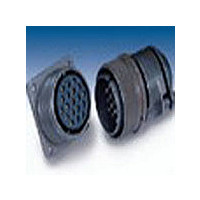
MS3106A10SL4S
Manufacturer Part Number
MS3106A10SL4S
Description
Manufacturer
Amphenol
Type
MIL-DTL5015 Circularr
Datasheet
1.MS3106A10SL4S.pdf
(73 pages)
Specifications of MS3106A10SL4S
Contact Gender
SKT
Gender
PL
Number Of Contacts
2POS
Shell Size / Insert Arrangement
10SL-4
Mounting Style
Cable
Termination Method
Solder
Shell Plating
Cadmium
Contact Plating
Silver
Body Orientation
Straight
Strain Relief
No
Contact Material
Copper Alloy
Contact Classification
2Signal
Operating Temp Range
-55C to 125C
Product Diameter (mm)
24.02mm
Product Length (mm)
37.28mm
Lead Free Status / RoHS Status
Not Compliant


MS/Standard
insert alternate positioning
To avoid cross-plugging problems in applications
requiring the use of more than one connector of the
same size and arrangement, alternate rotations are
available as indicated in the accompanying charts.
As shown in the diagram below, the front face of the pin
insert is rotated within the shell in a clockwise direction
from the normal shell key. The socket insert would be
rotated counter-clockwise the same number of degrees
in respect to the normal shell key.
Arrangement
Position W
10SL-4
12S-3
14S-2
14S-5
14S-7
14S-9
16-9
16-10
16-11
16-13
16S-1
16S-4
16S-5
16S-6
16S-8
18-1
18-3
18-4
18-8
18-10
18-11
18-12
18-15
18-20
18-22
18-29
20-3
20-4
20-5
20-6
20-15
20-17
20-18
20-19
20-21
Insert
View looking into front face of pin insert or rear of socket insert.
63
70
90
70
35
90
35
35
80
35
70
90
70
35
35
70
80
90
70
90
70
45
35
70
80
90
35
90
35
W
–
–
–
–
–
–
Position X
145
120
110
180
145
110
180
110
110
110
145
180
170
145
110
110
120
170
120
180
145
180
145
110
110
145
180
110
180
110
X
–
–
–
–
–
Degrees
215
240
270
215
250
270
250
250
250
215
270
265
215
250
250
240
265
240
270
215
270
215
250
250
215
270
250
270
250
Y
–
–
–
–
–
–
Position Y
290
290
325
325
325
280
325
290
290
325
325
290
280
290
290
325
290
280
325
325
Z
–
–
–
–
–
–
–
–
–
–
–
–
–
–
–
Arrangement
20-23
20-24
20-27
20-29
22-1
22-2
22-4
22-5
22-8
22-9
22-10
22-11
22-13
22-20
22-22
22-23
22-27
22-28
22-63
24-2
24-9
24-10
24-11
24-22
24-27
28-2
28-3
28-5
28-6
28-7
28-12
28-18
28-22
28-AY
32-2
Insert
Position Z
35
35
35
80
35
70
35
35
35
70
35
35
35
35
35
80
80
20
80
35
80
35
45
80
35
70
35
70
35
90
70
70
45
70
W
–
25
110
110
110
110
145
110
110
110
145
110
110
110
110
110
110
110
110
110
145
110
145
110
180
145
145
110
145
The following insert arrangements have the same alter-
nate insert rotations for W, X, Y and Z, which are:
X
–
–
–
–
–
–
–
–
Degrees
16-7
18-5
18-9
18-13
18-14
20-7
20-8
20-9
20-12
20-14
20-16
20-20
250
250
250
250
215
250
250
250
215
250
250
250
250
250
250
250
250
250
250
250
215
250
215
250
270
215
215
250
215
Y
–
–
–
–
–
–
325
325
325
280
325
290
325
325
325
290
325
325
325
325
280
280
280
325
280
325
280
325
290
325
290
325
290
290
290
20-22
22-6
22-12
22-14
22-15
22-16
22-17
22-18
22-19
22-21
22-24
22-25
Z
–
–
–
–
–
–
80
W
Arrangement
22-29
22-33
22-34
24-1
24-3
24-4
24-5
24-6
24-7
24-12
24-14
24-16
110
32-5
32-7
32-8
32-14
32-15
32-17
32-25
32-48
32-64
32-68
32-82
36-3
36-4
36-5
36-6
36-9
36-10
36-14
36-15
36-AF
40-1
40-5
40-9
40-10
40-35
40-AD
40-AG
40-AP
40-AV
X
Insert
Degrees
24-17
24-20
24-21
24-28
28-1
28-4
28-8
28-9
28-10
28-11
28-14
28-15
250
Y
35
80
80
65
35
45
60
80
80
30
30
70
70
35
80
80
90
60
65
65
33
65
65
70
45
37
35
90
W
–
28-16
28-17
28-19
28-20
28-21
32-1
32-3
32-4
32-6
32-9
32-10
32-12
280
Z
110
125
125
130
110
110
120
100
145
145
120
110
125
125
180
125
130
125
125
130
110
180
74
X
–
–
–
–
–
–
Degrees
32-13
32-22
32-AF
36-1
36-7
36-8
36-13
40-AR
40-AS
40-AT
40-AU
250
235
235
230
250
250
110
215
215
240
250
235
235
270
245
235
225
225
230
285
250
270
Y
–
–
–
–
–
–
–
325
280
280
295
280
250
290
290
325
280
280
305
300
270
310
310
290
322
325
Z
–
–
–
–
–
–
–
–
–
–
Related parts for MS3106A10SL4S
Image
Part Number
Description
Manufacturer
Datasheet
Request
R

Part Number:
Description:
CONN PLUG 3POS W/SOCKET SOLDER
Manufacturer:
Amphenol Industrial Operations

Part Number:
Description:
CONN PLUG 10POS W/SOCKET SOLDER
Manufacturer:
Amphenol Industrial Operations

Part Number:
Description:
CONN PLUG 5POS W/SOCKET SOLDER
Manufacturer:
Amphenol Industrial Operations

Part Number:
Description:
CONN PLUG 5POS W/PINS SOLDER
Manufacturer:
Amphenol Industrial Operations

Part Number:
Description:
CONN PLUG 6POS W/SOCKET SOLDER
Manufacturer:
Amphenol Industrial Operations

Part Number:
Description:
Cable Specification: PU CABLE, UL20549 24AWG*8C+AD,OD= 6.0mm
Manufacturer:
Amphenol